
Rainer Drath (University of Applied Sciences Pforzheim) · Markus Rentschler (Balluff GmbH) · Marco Hoch and Matthias Mueller (Mitsubishi Electric Europe B.V.)
Presented at
5th AutomationML User Conference
24–25 October 2018, Mölndal/Gothenburg, Sweden
Hosted by ABB
Type
Full paper, 10 pages
Open access
Republished by the AutomationML association. Copyright remains with the authors.
Abstract
To simplify the engineering of field devices, almost every fieldbus organization has developed its own Device Description Language (DDL), a formal language to describe the services and configuration options of field devices. The DDLs are usually tailored to the needs of the associated fieldbus engineering tool chain and unusable in tool chains of other vendors or in tools for other lifecycle phases. This paper describes a generic approach to overcome these shortcomings by means of AutomationML and provides an example for IO-Link masters and devices and for CC-Link IE Field devices. The proposed method is generic and re-usable for other DDLs.
Keywords: AutomationML; Device Description; EDD; FDCML; FDT; GSD; GSDML; IODD; IO-Link; CSP+; CC-Link XML
I. Introduction
Modern field devices for process and factory automation have a number of identification and configuration options and are customizeable to their individual use case. For this purpose they are usually equipped with a digital communication interface, such as IO-Link, HART, PROFIBUS, Fieldbus Foundation, Ethernet/IP, PROFINET, CC-Link, CC-Link IE Field, etc. Each of these communication standards has developed its own dedicated software tool ecosystem to control and configure the devices, usually based on a Device Description Language (DDL) approach, where a generic software can configure and control different devices through the interpretation of a Device Description (DD) associated to the individual device type. The economic benefit lies in the fact that the creation of a DD with the DDL requires much less effort than writing a dedicated software tool.
The newer XML-based formats such as GSDML, FDCML, ESI, CSP+ and IODD offer advantages compared to the traditional text-based formats GSD, EDDL and EDS, because they can rely on data model schematics (XSDs) and the related XML parser features for consistency checking of both syntax and semantics.
Whenever a field device is required, the DD file is loaded and interpreted by the engineering tool, providing user dialogs and functionality to enter property parameters in order to configure the individual device instance.
All devices of the same type have the same DD file, but the individual parameters of individual devices may have different parameter values dependent on the use case of a device. This illustrates general limitations of DDLs:
In many cases there is a strict split between type information and individual device information implies that type specific information is stored in the neutral DD file while the individual parameters are stored in the proprietary engineering tool. No tool independent storage of individual device configuration across the devices life cycle is established.
Once multiple field devices are interconnected into a communication network, the topology configuration is stored in the proprietary engineering tool. There is no tool independent archiving, distribution, re-use or further re-use of topology configurations available.
This paper presents a method to overcome both issues by utilizing AutomationML and provides examples for IO-Link components in an automation systems (see devices of type Master and Device in Fig. 1) and CC-Link IE Field. Clause II mentions related work and existing fieldbus standards, clause III defines requirements for fieldbus topology modelling, clause IV provides an example for IO-Link topologies, whereas clause V does the same for a CC-Link IE Field topology with IO-Link components. Finally, clause VI discusses potential use cases and clause VII summarizes the findings and gives an outlook into next steps of this research.
Fig. 1 (basic structure of an automation system with fieldbus and IO-Link) is available in the original PDF.
II. Related Work
A. Fieldbus technologies
An overview of the integration issues for fieldbus technologies is presented in [2-3], additionally the horizontal, vertical and lifecycle integration problem is outlined in [3].
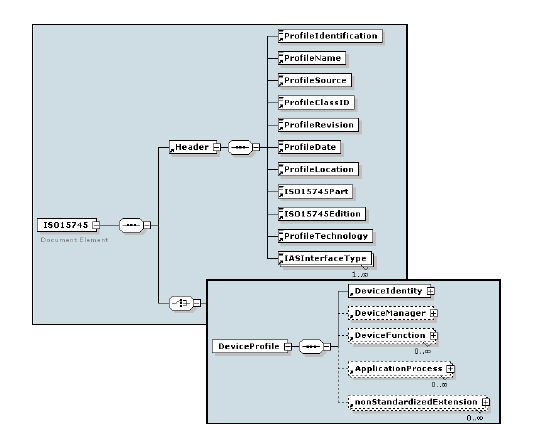
Regarding horizontal integration, IEC 61158 lists 79 existing communication technologies and describes an approach how all fieldbus technologies could be brought to an unified foundation, whereas IEC 62390 attempts to unify device profiles. Device controller programming is standardised in IEC 61131. The overall integration is covered by ISO 15745, providing a sophisticated data model for device descriptions (see Fig. 2). An early adoption of ISO 15745 for a system neutral DDL was the Field Device Configuration Markup Language (FDCML) [4], which could not gain widespread acceptance.
B. Existing DDL standards
In this chapter, some existing DDL standards are shortly presented, see also [2-3]. The main weakness of these existing fieldbus standards are their incompatibility and insufficient suitability for horizontal and lifecycle integration.
1) EDDL
The Profibus Nutzerorganisation (PNO), Fieldbus Foundation, HART Communication Foundation, OPC Foundation and FDT Group have created the EDDL Cooperation Team (ECT) and merged their individual dialects of the DDL. The result was the Electronic Device Description Language (EDDL), which does not make use of XML and was published as IEC 61804. It is mainly used in the process automation industry.
2) EDS
The ODVA maintains the Ethernet/IP fieldbus standard, where the Electronic Data Sheets (EDS) describe how a device can be used on an EtherNet/IP network. It describes the objects, attributes and services available in the device, not making use of XML. They contain an ASCII representation of a device’s parameter objects and some additional information required for object addressing. There are discussions within ODVA to generate an XML based EDS format in the future [5].
3) ESI
For the EtherCAT fieldbus, every EtherCAT device must be delivered with an EtherCAT Slave Information file (ESI), a device description document in XML format [6]. The structure of an ESI file is defined in the EtherCATInfo.xsd XML schema document (Fig. 3). EtherCAT is also part of ISO 15745-4.
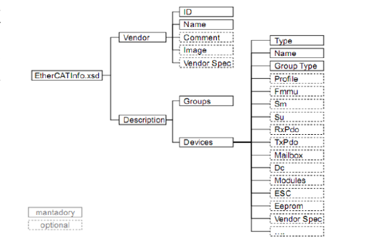
Information about device functionality and settings is provided by the ESI, whereas the EtherCAT Network Information File (ENI) describes the network topology, the initialization commands for each device and the commands which have to be sent cyclically [7]. The ENI file is provided to the master, which sends commands according to this file.
4) GSDML
The characteristics of a PROFINET IO Device are described by the manufacturer in a General Station Description (GSD) file, providing the engineering and supervision software with a basis for configuring and monitoring the devices of a PROFINET IO system. The language used for this purpose is the GSDML (GSD Markup Language) – an XML based language that structurally complies to ISO 15745-1.
5) POWERLINK XDD
The Ethernet Powerlink XML Device Description [8] complies to ISO 15745-1 and defines the following file types:
- The profile definition file (XPD) is an XML representation of a POWERLINK framework, device profile or application profile.
- The device description file (XDD) models the device type of a POWERLINK device, to be used as a blueprint for instantiation of devices in an actual network configuration. An XDD file contains the default values of the device but no commissioning values and no actual values.
- The device configuration file (XDC) describes a configured POWERLINK device and stores the information for a specific instantiation of a device in a specific network environment. All information from the XDD file plus actual values and/or device commissioning values can be stored in an XDC file.
6) CSP+
The CC-Link Partner Association (CLPA) maintains the CC-Link family network standards, where the Control & Communication Profile (CSP+) describes how a device can be used in a CC-Link family network [16][17][18]. CSP+ files are written in XML.
In the CSP+ model, the modules are separated into virtual field devices which represent the communication function related information and into virtual control devices which represent the module-specific information and functionality.
A CSP+ file consists of four sections. A FILE section which describes management information of the CSP+ file itself, a DEVICE section which describes information about the module such as name, identification and specifications, a BLOCK section which describes the virtual control devices and a COMM_IF section which describes the virtual field devices. For each module function a BLOCK section and for each supported communication protocol a COMM_IF section exists in the CSP+ file.
In this way different communication protocols, e.g. CC-Link and CC-Link IE Field, can be integrated in the same format.
7) IODD
IO-Link was developed by the IO-Link consortium and has first been published in 2006 [1]. In 2010 it was integrated into IEC 61131-9 as “Single-drop digital communication interface for small sensors and actuators” (SDCI). IO-Link is not a fieldbus, but a non-TCP/IP serial point-to-point communication protocol designed to communicate with both analogue and digital sensors and actuators on the last meters in the field level (see Fig. 4).
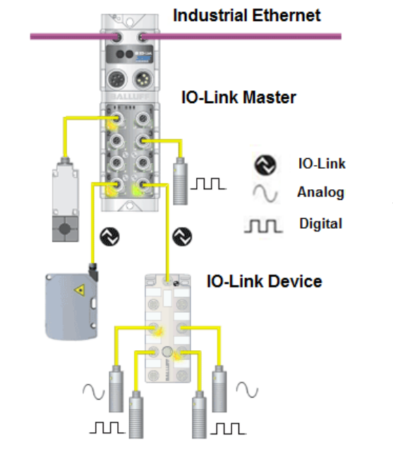
Every IO-Link device must be delivered with an IO-Link Device Description File (IODD), a device description document in XML format. The IODD complies to ISO 15745-1. A dedicated DD format of IO-Link Masters is not defined by the IO-Link consortium, instead they are usually covered within the fieldbus DDs, which has often shown to be a weakness of the IO-Link ecosystem in terms of horizontal and lifecycle integration.
C. AutomationML
AutomationML is a neutral data format based on XML. It has been initiated by Daimler in 2006, its architecture is specified in the IEC 62714 part 1 [9]. Its lean and distributed architecture interconnects existing established file formats for different domains [10]. With CAEX (IEC 62424, [11]) it allows to store object models following the object oriented paradigm, covering class libraries, interfaces, attributes, links, and instances modelled in instance hierarchies. Furthermore it has the functionality to reference external formats. AutomationML covers the modeling of geometry via the file format COLLADA and discrete logics via PLCopen XML.
D. AutomationML communication modeling
A working group within the AutomationML community has developed a generic and technology independent proposal how to model communication networks with AutomationML [12]. An application example for Ethernet/IP was presented in [13]. Key elements of this modeling is a strict separation of the physical network that models the physical wiring of the network infrastructure, and the logical network that models the logical interconnections in the communication network. Consequently, the AutomationML communication white paper comprises a set of role classes for physical and logical network items and a set of technology independent interface classes. Furthermore, it describes how to apply these technology independent roles and interfaces in order to model technology specific communication networks. However, the embedding of DDLs is not covered.
III. Requirements for Modeling Fieldbus Topologies
A. General concept
The key question is: how can configurations and topologies be modeled based on the limited classical DDs? The most obvious approach is be to extend the classical DD standards, but this requires long term standardization cycles and would reduce acceptance in industry. The approach presented in this paper intends to keep the existing standards and allows immediate applicability by using AutomationML in the way it has been designed for: AutomationML becomes the glue.
The idea of the presented concept is to add an AutomationML model on top of DD models. The classical Device Descriptions deliver the type information of devices, while AutomationML provides classes and also instances with individual configurations, and the modelling of hierarchies and links between object instances.
The following basic requirements must be fulfilled by the AutomationML-based engineering solution approach for modelling fieldbus configurations and topologies.
B. Requirements related to Device Descriptions
- As in the existing fieldbus solutions, the AML-based solution must provide one AML file per DD file for each device type, called DD.AML. All DD information of one device type are modelled in one SystemUnitClass within one DD.AML file.
- For a single device instance, the same DD.AML shall be used, but with individual parameter values and identifiable via a dedicated ID. Thus the user shall be able to clearly assign one DD.AML file to one specific individual device in his network.
- The AML-based solution must be able to reference within the DD.AML to an existing classical DD file. The mapping of the parameters of that classical file to the AML representation must be defined by the respective fieldbus organisation that wants to support the AML approach.
- It must be possible to manage libraries of DD.AML models in DD.AMLX containers [14].
- Self-explainable naming conventions for DD.AML and DD.AMLX files must be defined.
- DD.AML files should only model needed data. When an existing classical DD or an DD.AML library is referenced, only the required instance parameter values shall be modelled, all data that is not required or unchanged is not explicitly modelled. This results in slim DD.AML files.
C. Requirements related to connections
- The AML-based solution must provide the ability to model connections.
- The AML-based solution must support connection types in a similar way as device types thus describing cable and connectors as products. This can be achieved in separate connection description files, called CD.AML or containers thereof (CD.AMLX). For instances of connections, the same CD.AML files can be used, but with differing parameter values (i.e. cable length and connection name) and individually identifiable via a dedicated ID.
- Thus the user shall be able to clearly assign individual connections in his network to CD.AML files.
D. Requirements related to fieldbus topology descriptions
- A topology graph basically consists of nodes (devices with interfaces) and edges (connecting interfaces).
- The AML-based solution models device types as CAEX SystemUnitClass, device instances as CAEX InternalElements and Interfaces as CAEX ExternalInterfaces.
- Edges should be modelled as CAEX InternalElements with individual interfaces. The modelling of Edges as individual objects allows modelling of e.g. physical cables. Even logical connections could be objects. The interfaces of an Edge can be connected to Interfaces of the devices via CAEX InternalLinks.
- The AML-based solution must be able to model arbitrary topologies of automation devices in one (TD.AML) or more files (TD.AMLX). A clear distinction between e.g. hierarchical, logical, and physical topology must be modelled in the same AML topology file.
- It must be possible to model different physical topologies in the same AML topology file(s), such as power wiring, communication wiring, or even installations of different technologies, such as pneumatic pipes between devices.
- An overall topology model file must be able to make use of multiple underlying topology files. A topology model file basically consists of the following sections: list of underlying topology files (if any), hierarchical list of nodes with their associated interfaces (can point to underlying DD.AML files), list of connections between nodes in this and the underlying files.
IV. Proposal for Modeling IO-Link Topologies
A. General concept
This chapter illustrates the previously described basic concept ideas of modelling fieldbus topologies exemplarily by means of IO-Link. IODDs deliver the type information of IO-Link devices, while AutomationML provides classes and also instances with individual configurations, and the modelling of links between object instances. For IO-Link masters, an AML-based device description schema has to be developed.
In the first step, following the recommendations of the AutomationML communication working group, the authors developed technology specific AutomationML classes. In the second step, IO-Link master and device type libraries are modelled within AutomationML class libaries, referencing the original DDs. From here, the device types can be instantiated and parameterized individually enabling the neutral storage of IO-Link master and device configurations. Third, the full IO-Link example topology is modelled.
B. Example
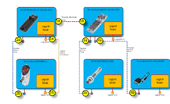
Fig. 5 illustrates an example IO-Link topology comprising two IO-Link masters and three IO-Link devices connected via IO-Link cables.
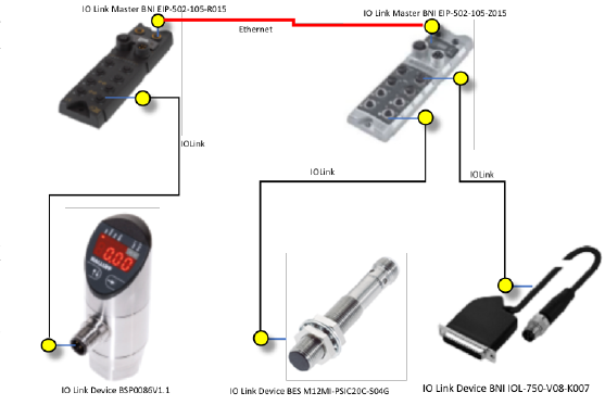
Fig. 6 illustrates the IO-Link topology in more detail with physical and logical connections. In addition, both IO-Link masters are connected with each other via an Ethernet connection. Furthermore, both IO-Link masters are connected via a power supply daisy-chain, not shown in the figure. Hence, this example combines three different physical networks.
Fig. 6 (schematics of the logical and physical networks of the IO-Link topology example) is available in the original PDF.
C. Step 1: Developing technology specific role classes
The first step for modelling the topology example is the development of specific role class libraries for each used technology IO-Link, Ethernet and PowerPort, as shown in Fig. 7:
- ExampleIOLinkRoleClassLib,
- ExampleEthernetRoleClassLib and
- ExamplePowerPortRoleClassLib
These classes only illustrate the method, all role classes currently have no further attributes, those may be added later.
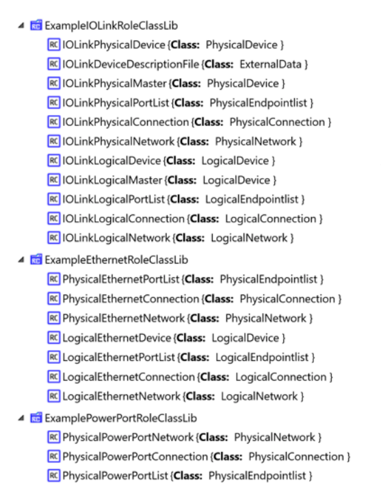
These libraries comprise 21 role classes and form the basis for the AutomationML modelling of IO-Link topologies. All role classes are derived from the AutomationML communication white paper [12], except the role IOLinkDeviceDescriptionFile which is derived from the role class ExternalData [15]. This role is of importance for the presented concept: it activates the ability of AutomationML to model and to reference documents in the AutomationML object model.
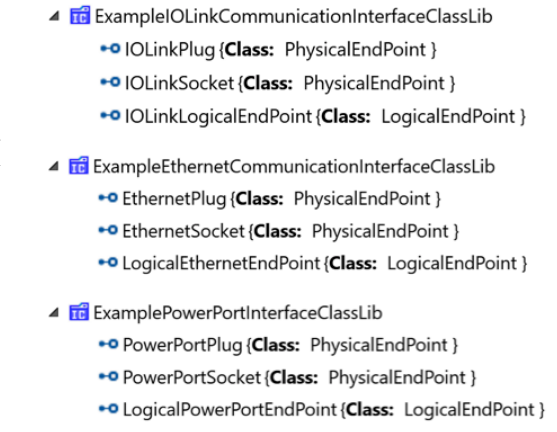
Based on the recommendations of the AutomationML communication working group [12], the authors derived technology dependent interface classes for the IO-Link-, Ethernet- and PowerPort-wiring. These classes model literally the interfaces: the plugs and sockets and a related logical end point of each of the mentioned technologies, see Fig. 8.
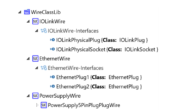
Finally, we need models for the physical wires of all three required technologies. Those are modelled in a user defined CAEX system unit class library containing the classes IOLinkWire, EthernetWire and PowerSupplyWire. Fig. 9 shows the classes with each individual end points: the IO-Link wires have a plug and a socket, while Ethernet wires have two plugs. PowerPort has multiple configurations, the present example models a wire with two plugs.
All mentioned classes form the basis for the modelling of IO-Link device configuration as well as IO-Link topologies. They can be re-used across multiple IO-Link use cases: for the modelling of the configuration of a single and individual IO-Link device configuration up to complex networks of multiple master and device topologies including the PowerPort daisy chain and the Ethernet network connecting the IO-Link masters.
D. Step 2: Modelling of IO-Link devices and masters in AutomationML
Utilizing these new roles, the IO-Link device and master types must be modelled each as AutomationML class. In order to model the example, the authors developed a vendor specific system unit class library with all required example IO-Link devices that directly reference the related IODD files. Fig. 10 shows this by means of the IO-Link device BSP0086. This class contains an internal element IOLinkDescriptionDocument that references its related IODD file with an attached external interface named DocumentLink. The interface models the binding of the AML device class to the IODD file. The CAEX attribute refURI of this interface references the physical IODD file. The CAEX attribute MIMEType of this interface is set to “application/xml” in order to indicate that this IODD file is an XML file. Furthermore, the class models the logical node of the device, and one physical IO-Link plug.
Fig. 11 and Fig. 12 show the system unit classes for the devices BES M12MI-PSIC20C-S04G and BNI_IOL-750-V08-K007. The architecture of the models are identical to the previous IO-Link device.
Parameters of the device types from the IODD files are re-modeled in the AutomationML classes in order to mirror them in the AutomationML space. This means, that the IODD parameters are now available in the AutomationML class model and can be utilized on instance level.
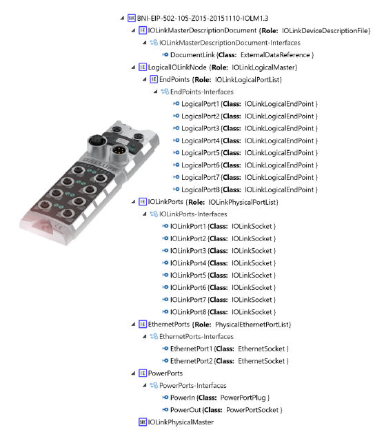
Fig. 13 and Fig. 14 illustrate the AutomationML classes for two IO-Link master examples: BNI-EIP-502-105-R015 and BNI-EIP-502-T015-105-Z015. The mechanism to reference the related device description is identical. The masters have, in difference to the IO-Link devices, multiple ports, and each physical port has a logical counterpart. Furthermore, each master has two Ethernet ports and two power ports. Further ports could be added, the focus in this example was not in the completeness, but in the general modelling principles.
Not part of this research but a useful next step is to automatically generate those libraries by reading and converting libraries of IODD and Master-DD-files (IOLM) into AutomationML system unit classes. A unified IOLM-DD standard does yet not exist and is recommended to be created entirely out of AutomationML in the continuation of this work.
Fig. 10, Fig. 11, Fig. 12 and Fig. 13 (IO-Link device and master models referencing external IODD/IOLM files) are available in the original PDF.
E. Step 3: Modelling the IO-Link topology
Since the object modelling in AutomationML bases on CAEX, all classes can be instantiated in a CAEX InstanceHierarchy. The instance hierarchy represents a concrete project or configuration. Here, according to the modelling recommendations [12], in the first level below the root object, the authors model the logical network, the physical IO-Link network, the physical Ethernet network, the physical PowerPort network, and the master instances.
The master object contains nested objects which are predefined in the related classes. Additionally, the belonging IO-Link devices are modeled. Fig. 16 illustrates the interlinking between ports connecting the end points of physical or logical wires to the related ports.
The resulting AutomationML file now contains all required standard AutomationML libraries, all IO-Link device and master classes and the individual configuration.
Fig. 15 (the instance hierarchy of the IO-Link topology) is available in the original PDF.
V. Proposal for Modelling CC-Link IE Field Topologies
A. General concept
This chapter illustrates the previously described basic concept ideas of modelling fieldbus topologies exemplarily by means of the Ethernet based CC-Link IE Field network. CSP+ files deliver the type information of CC-Link IE Field devices, while AutomationML provides classes to assign commonly understandable semantics and also instances which contain the individual configuration information. Additionally AutomationML enables the modelling of links between object instances. In case of CC-Link IE Field, both Master and Slave devices are described by CSP+ device description files.
In the first step, following the recommendations of the AutomationML communication working group and in alignment with the previous chapter, the authors developed technology specific AutomationML Role and Interface Classes. In the second step, CC-Link IE Field device type libraries are modelled within AutomationML System Unit Class Libaries, referencing the original DDs and adding additional engineering information (e.g. physical/logical ports) to model the topology in AutomationML. From here, the device types can be instantiated and parameterized individually enabling the neutral storage of CC-Link IE Field device configurations. Third, the full CC-Link IE Field network topology is modelled exemplary.
B. Example
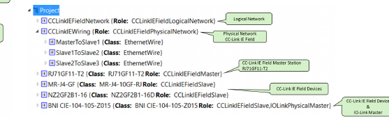
Fig. 17 illustrates an example CC-Link IE Field topology comprising of one CC-Link IE Field master and three CC-Link IE Field slave devices connected via compatible Ethernet cables. The following modules are used:
- RJ71GF11-T2 (CC-Link IE Field Master)
- MR-J4-10GF-RJ (Servo Amplifier)
- NZ2GF2B1-16D (16 points DC Input module)
- BNI CIE-104-105-Z015 (CC-Link IE Field IO-Link gateway)
The CC-Link IE Field IO-Link gateway module can be seen as an IO-Link master. Hence, in later steps, this example could be extended with the modelling of an IO-Link configuration below this master module.
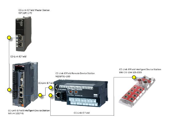
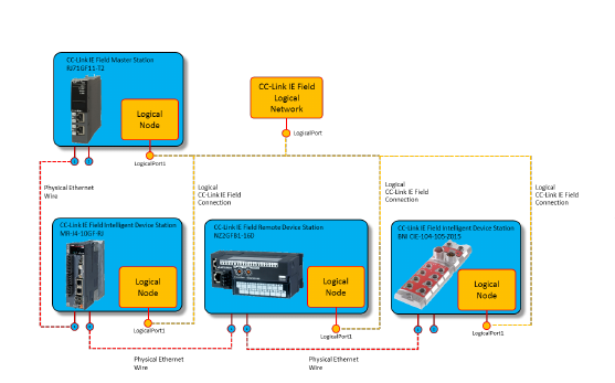
Fig. 18 illustrates the CC-Link IE Field topology in more detail with physical and logical connections.
C. Step 1: Developing technology specific role classes
The first step for modelling the example is the development of specific role class libraries for the additionally used technology CC-Link IE Field as shown in Fig. 19. The role class libraries for IO-Link, Ethernet and PowerPort, as shown in Fig. 8 will be reused in this example. These classes only illustrate the method, all role classes currently have no further attributes, which may be added later.
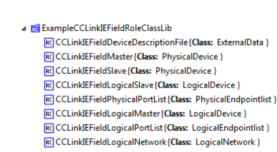
This library comprises 8 role classes and forms the basis for the AutomationML modelling of CC-Link IE Field topologies. All role classes are derived from the AutomationML communication white paper [12], except the role CCLinkIEFieldDeviceDescriptionFile which is derived from the role class ExternalData [15]. This role is of importance for the presented concept: it activates the ability of AutomationML to model and to reference documents in the AutomationML object model.
Based on the recommendations of the AutomationML communication working group [12], the authors derived a technology dependent interface class for the CC-Link IE Field logical connections. For the physical connections the previously defined EthernetWiring Interface Class Library is reused.

Classes for modeling the actual wiring as shown in Fig. 17 of the example above are reused.
All mentioned classes form the basis for the modeling of CC-Link IE Field device configurations as well as network topologies in a vendor neutral way so that the configurations and topologies can be seamlessly exchanged between various tools in the engineering process.
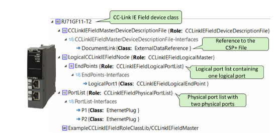
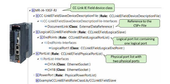
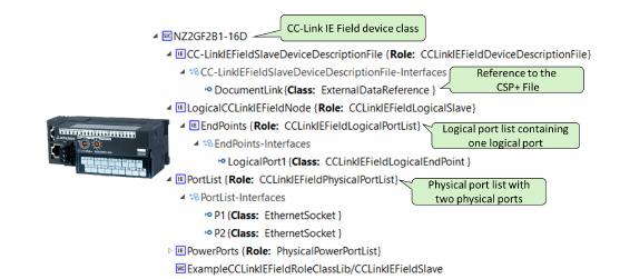
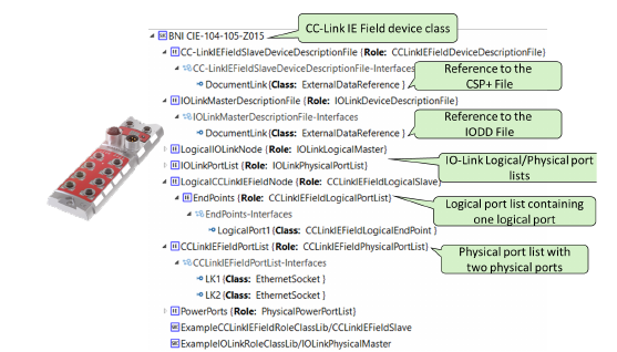
D. Step 2: Modelling of CC-Link IE Field devices and masters in AutomationML
Utilizing these new roles, the CC-Link IE Field device types can be modelled each as an AutomationML System Unit Class. The authors developed a sample System Unit Class Library for each device shown in Fig. 21, Fig. 22, Fig. 23 and Fig. 24, that directly reference their related CSP+ files. Therefore each System Unit Class contains an internal element CCLinkIEFieldDescriptionFile that references its related CSP+ file with an attached external interface named DocumentLink. The CAEX attribute refURI of this interface references the physical CSP+ file. The CAEX attribute MIMEType of this interface is set to “application/xml” in order to indicate that this CSP+ file is an XML file. Furthermore, each class models the physical and logical ports of the device.
E. Step 3: Modelling the CC-Link IE Field topology
Since the object modelling in AutomationML bases on CAEX, all classes can be instantiated in a CAEX InstanceHierarchy. The instance hierarchy represents a concrete project or configuration. Here, according to the modelling recommendations [12], in the first level below the root object, the authors model the logical network, the physical CC-Link IE Field network as well as the device instances.
The resulting AutomationML file (see Fig. 25) now contains all required standard and technology specific AutomationML Role Class and Interface Class Libraries, all CC-Link IE Field device types as System Unit Classes and the individual configuration and topology in the Instance Hierarchy.
VI. Discussion and Use Cases
The proposed approach combines the benefits of the classical DD concept (in this example case IODD and CSP+) related to type information and AutomationML capability to model one or multiple instances and their relations. This keeps the well-defined and established IODD and CSP+ standards and tool ecosystems unchanged and provides investment protection for related stakeholders and tool vendors. But it opens the door to overcome the unsatisfactory usability across tool chains for other lifecycle phases. Well-engineered configurations of devices can now be stored as AutomationML files and even further enriched with additional information, such as CAD and other model data. The following basic use cases can be satisfied with the new approach:
- Export and archiving of device configurations or network topologies such as IO-Link or CC-Link IE Field in a neutral format, out of the proprietary engineering tool. This makes the data independent of the tool and leads to more independence on tools. It provides investment protection for the data and promises future readability of data that are usually encapsulated in proprietary engineering tools.
- Transfer of those configurations between engineering tools. This is useful when suppliers perform the configuration with their own best-of-class tool and need to transfer the results into the customer engineering tools, or if one engineering tool is going to be replaced by another engineering tool.
- Distribution of device configurations on a server or cloud for later re-use in other projects, to share them with customers, and to enable new services and business options in a future engineering market place. For instance, when devices are exchanged by newer generations of devices, a future cloud-based configuration service may automatically find suited parameter sets to automatically configure the new devices and may actively ask for open questions.
- Configuration of Digital Twins (e.g. an OPC UA server) by the upload of device configurations of a future IO-Link device or master into the digital twin. This typical Industry 4.0 use case would enable data access to upcoming software services like consistency checks, maintenance services or data mining.
There are more possibilities, the mentioned use cases are only a first initial collection.
VII. Summary and Outlook
The proposed approach overcomes the issue that DD files are neither able to store individual device configurations but type information only and are not easily extendable, nor they are suited to model fieldbus topologies in a vendor independent way. A generic approach with AutomationML has been proposed, which allows to include classic DDs into an AutomationML wrapper that can contain the glue and all further missing specification items, such as mechanical, electrical and configuration information or even fully replace the classic DD.
The generic problem has been exemplarily investigated by means of the IO-Link and CC-Link IE Field standards, but the proposed solution can be applied to all other fieldbus standards. The ability of AutomationML to remove unchanged data in comparison to the class definition allows to easily shrink the XML code to the essence of modified data. This keeps the AutomationML DD files short and readable and increases the industrial acceptance rate.
The next step in this investigation will be the modelling of complex hierarchical topologies across multiple topology files. This will be developed in future according to the AutomationML communication white paper.
The AutomationML Application Recommendation AR APC [19] describes the exchange of Hardware Configurations, IO-Labels and Network Configurations between ECAD and PLC engineering tools. The described approach will be aligned with the AR APC [19] document in the future as well.
A further recommendation is to automatically generate the AutomationML system unit classes by scanning the DD files and converting them into AutomationML classes. Finally, the authors aim for bringing this research results into the IO-Link community and other fieldbus organizations in order to develop a method for the establishment of AutomationML-based device description files.
References
[1] IO-Link consortium: “IO-Link Interface and System Specification”, Version 1.1.2, July 2013.
[2] N. Siltala: “Formal Digital Description of Production Equipment Modules for supporting System Design and Deployment”, Doctoral Thesis, Tampere University of Technology, 2016.
[3] A. Gössling: “Device Information Modeling in Automation – A Computer-Scientific Approach”, Doctoral Thesis, Technical University Dresden, February 2014.
[4] IDA GROUP: “FDCML 2.0 Specification Version 1.0”, fdcml.org, 2017.
[5] R. Blair: “A Modern Approach to CIP Device Descriptions”, ODVA 2015 Industry Conference, Frisco, Texas, USA.
[6] ETG.2000 EtherCAT Slave Information (ESI) specification.
[7] ETG.2100 EtherCAT Network Information (ENI) specification.
[8] EPSG Draft Standard 301 (EPSG DS 301), Ethernet POWERLINK, Communication Profile Specification, Version 1.3.0.
[9] IEC 62714: Engineering data exchange format for use in industrial automation systems engineering (AutomationML) (2012).
[10] R. Drath: Data exchange in plant design with AutomationML. Integration with CAEX, PLCopen XML and COLLADA. Springer (VDI-Buch), Heidelberg (2010).
[11] IEC 62424: Representation of process control engineering – Request in P&I diagrams and data exchange between P&ID tools and PCE-CAE tools. August 2009.
[12] AML Best Practice Recommendations: Communication, V1.0.0, checked at 11.02.2018.
[13] F. Bendik, A. Lüder, N. Schmidt: “Exchange of engineering data for communication systems based on AutomationML using an EtherNet/IP example”, ODVA 2015 Industry Conference, Frisco, Texas, USA.
[14] AML Best Practice Recommendations: AutomationML Container, Document Identifier: BPR Container, V1.0.0, October 2017.
[15] AML Best Practice Recommendations: ExternalDataReference, BPR 005E, V1.0.0.
[16] Control & Communication System Profile Specification, BAP-C2008ENG-001-C, published June 2017 by CLPA.
[17] CSP+ Creation Guidelines – Outline, BAP-C3001ENG-001-C, published October 2017 by CLPA.
[18] CSP+ Creation Guidelines – CC-Link IE Field Network detail version, BAP-C3001ENG-003, published September 2016 by CLPA.
[19] AML Application Recommendation: Automation Project Configuration (AR APC), V1.0.0.
BibTeX
@inproceedings{drath2018fieldbus,
  author    = {Drath, Rainer and Rentschler, Markus and Hoch, Marco and Mueller, Matthias},
  title     = {Vendor-Independent modeling and exchange of Fieldbus Topologies with {AutomationML}},
  booktitle = {Proceedings of the 5th AutomationML User Conference},
  address   = {M{\"o}lndal, Sweden},
  month     = oct,
  year      = {2018},
  publisher = {AutomationML e.V.},
  url       = {https://www.automationml.org/conferences/conference-highlights/vendor-independent-modeling-and-exchange-of-fieldbus-topologies-with-automationml/}
}
How to Cite
R. Drath, M. Rentschler, M. Hoch, M. Mueller: “Vendor-Independent modeling and exchange of Fieldbus Topologies with AutomationML”, Proceedings of the 5th AutomationML User Conference, Mölndal, Sweden, 24–25 October 2018.
This page is a text rendering of the original conference paper, published for accessibility and search. The PDF is the authoritative version. Figures 1, 6, 10, 11, 12, 13 and 15 are available in the PDF. If you are an author and would like a correction, please contact office@automationml.org.