
Arndt Lüder, Johanna-Lisa Pauly and Konstantin Kirchheim (Otto-von-Guericke University, Faculty of Mechanical Engineering, Magdeburg) · Felix Rinker and Stefan Biffl (TU Wien, Institute of Information Systems Engineering; CDL-SQI)
Presented at
5th AutomationML User Conference
24–25 October 2018, Mölndal/Gothenburg, Sweden
Hosted by ABB
Type
Full paper, 6 pages
Open access
Republished by the AutomationML association. Copyright remains with the authors.
Abstract
Within the overall lifecycle of production systems the engineering phase gains higher importance. Hence, companies focus more and more on the quality and efficiency of engineering processes. The exchange of engineering data within these processes seems promising in terms of optimization potential. Nevertheless, improving the data exchange of engineering data is a difficult task and selecting an appropriate data exchange format is not enough. Several possible obstacles need consideration within this process. This paper discusses selected major challenges for engineering data exchange process improvement and how to apply AutomationML to overcome these challenges.
Keywords: Production system engineering, Engineering data exchange, AutomationML, Engineering process migration
I. Introduction
The exchange of engineering data was identified as a factor with influence on speed, quality and reliability of engineering data even before discussions about Industrie 4.0 have started [1], [2]. Various data exchange technologies were developed and discussed in science and application areas. However, up to now there are still major challenges open in engineering data exchange like data integration and consistency or multimodel based engineering [3].
These challenges are less related to technology aspects but more to management issues. The engineering of production systems usually follows a multidisciplinary approach. The related engineering activities result in an engineering network in which several engineers are involved who use different engineering tools [3]. These engineering networks are embedded within the overall production system lifecycle [4], while life cycles of different production systems are interrelated [3], see also Figure 1. Hell [5], for example, has shown that the engineering of welding lines in the automotive industry contains more than 30 engineering steps with the same number of engineering tools. The welding process can be embedded as part of a network of different engineering projects for similar welding systems.
Fig. 1 (production system life cycle dependencies) is available in the original PDF.
In these engineering networks the exchanges of engineering data consist of a mixture of the following data exchange basic patterns:
- Multiple transmissions of stepwise improved, e.g. enriched, engineering data from a data source to a data sink.
- Transmission of engineering data from one data source to multiple data sinks.
- Transmission of engineering data from several data sources to one data sink.
- Round-trip data exchange from a data source to a data sink, which sends an updated version of the engineering data back to the original data source.
In general, the resulting engineering networks can be considered as a data logistic system. This system consists of several data sources and data sinks which send or receive engineering data (see Figure 2) and use a data exchange. A data source and data sink may be the same entity. Our initial analysis in the field of file-based data exchange shows the most frequently used data formats for the data exchange to be *.xml, *.csv, and *.pdf.
Fig. 2 (abstract engineering data logistic system) is available in the original PDF.
Changes of structure or behaviour in a single or multiple parts of engineering networks may impact the whole data logistic, its elements, and its internal behaviour. Therefore, changing the data logistic is potentially risky and expensive. On the upside, the benefits of integrating additional functionalities into the engineering data logistics may provide a significant business advantage.
Hence, engineering data logistics improvement needs both an appropriate architecture of the engineering data logistics (i.e., the technologies applied within the engineering network) and a detailed structure for managing the improvement process. This paper will provide such a process.
The remainder of this paper is structured as follows. Section II characterizes the main challenges related to an engineering data logistics, showing which additional functions might be integrated in an engineering logistics, and main obstacles currently hindering the improvement of engineering data logistics. Section III introduces an abstract engineering data logistics architecture consisting of a centralized data exchange structure and flexible system adapters. Section IV discusses how to exploit this architecture with a migration process applicable to improve the engineering data exchange. Section V discusses the benefits from using AutomationML within the implementation of the architecture and the migration process. Section VI illustrates a successfully implemented application example. Section VII concludes with ideas for further research and development.
II. Challenges in Engineering Data Logistics
The following obstacles were derived in a deductive approach. For this, several discussions with academic and industrial experts, members as well as non-members of the AutomationML Association, have been considered. The identified obstacles are valid for the improvement and enlargement of data logistics as described in this paper. They are not exhaustive but are mainly considered as the most important ones. Therefore, it has to be taken care of them when thinking about a migration process towards an improved data logistic.
The following main obstacles were identified:
- Engineering habit: In many contexts, engineers optimize their local and discipline-specific processes. The processes are needed for key design decisions in their discipline. They have dedicated engineering tools supporting their processes and know how to use these tools. As their KPIs are related to the efficiency and quality of the engineering results the engineers try to avoid changes in their optimized local settings.
- Tool diversity: Engineering tools applied within the different engineering habits are based on discipline-specific concepts. Therefore, these tools were developed on the foundation of discipline-specific data structures and procedures. These concepts, data structures, and procedures are not necessarily consistent with each other across tools.
- Economic meaningfulness of migration: The improvement of data logistics within engineering networks needs to be economically beneficial to the engineering organization. As complex improvements are usually costly and risky, improvements need to be made and evaluated incrementally. Each improvement step has to provide benefits to the engineering organization.
Beyond these obstacles, the engineering data logistics may provide the following functions. They address existing challenges in the data exchange in engineering networks.
- Change management: The artifacts exchanged in an engineering network may have different levels of completion, even if they describe the same object. It is necessary for each data sink to identify already known information and their change state when receiving data.
- “White spot” management: A defined amount of information is needed for the execution of an engineering activity. A data sink should be able to identify missing information for the execution of an engineering activity and the data source this information shall come from.
- Consistency management: More than one engineering discipline handles engineering data on the same object to be engineered. These engineering data may be interrelated following natural or economical laws. Hence, data sources and sinks need to be able to check the consistency of engineering information within and across discipline borders.
The improvement process of a data logistic needs to pay attention to all these obstacles and challenges.
III. Basic System Architecture
The data logistic shall be based on two parts. On the one hand it is based on local domains for domain-specific information. On the other hand, there is a centralized domain which contains information about the whole system to be engineered.
The engineering data shall be transported from the local domains of the data sources via the global domain to the local domains of the data sinks. A transformation is needed as the domain-specific tools use data structures which do not necessarily fit to each other. The data structure of the global domain acts as relay station.
The necessary functions for change management, white spot management, and consistency management are provided by the global domain. The data transformations can decouple the different tools involved in the local domains. Figure 3 gives an overview of the resulting structure.
Fig. 3 (architecture of engineering data logistics) is available in the original PDF.
The central information domain shall realize data aggregation based on a common data model to support functions for change management, white spot management, and consistency management [6].
Beyond, the domain-specific engineering tools can follow their own data models within the local domains which fit best to the related domain.
IV. Migration Process
In [7], Calá et al. describe an approach applicable as migration process towards Industrie 4.0 based control systems. This approach can be adapted to a migration approach, which can be used to improve a data logistic.
To overcome the obstacles named above, the migration process shall be a stepwise approach. In each step one part of the data logistics is identified to be improved next. The single improvements lead to the improvement of the overall system capabilities and aims at a positive ROI from the individual change.
At first, the long-term visions and the short-term goals of the migration process have to be distinct (see Figure 4). The long-term vision is the improvement of the whole data logistic, the short-term goal establish the single steps of improvement. The proposed stepwise process follows a lean approach [8] in order to support the continuous improvement of the data logistics even if the conditions are unclear and uncertain.
The objective of the migration process is to define a general suitable path towards the long-term vision. In doing so, a set of short-term goals are reached which consist of a sequence of migration steps for each short term goal. Thus, the migration path consists of several migration steps that represent different solution options to achieve the final goal.
Single migration steps need to be investigated and evaluated while different decision goals and constraints are taken into account to identify a suitable migration path.
![Fig. 4. Illustration of steps in an example migration path [7]](https://www.automationml.org/wp-content/uploads/2026/08/AML-2018-Lueder-Migration-to-Tool-Chains-fig1.png)
The process starts with the Preparation phase in which the existing engineering data logistic is analysed. The long-term vision, respectively the overall improvement of the data logistic is defined.
In the Options Investigation phase, different migration solutions are collected and evaluated, in order to identify suitable migration steps towards the target system following the long term vision. These options can be, for example: the integration of a new local domain; a new tool in a local domain; a new data set coming from an already involved tool; the realization of a new management function within the global domain.
The selected option is then detailed within the Design phase, in which the integration of new data or new functions in the existing system is defined. After a feasibility study of the designed solution, it can be implemented and verified within the Implementation phase.
The improved engineering data logistics is validated in the Deployment phase.
Once the first step of migration is performed, it is possible to start again from the Preparation phase. Starting with the analysis of the current state of the system, over the definition of the next migration steps until the long-term vision of the improvement of the data logistic is reached.
V. Use of AutomationML
AutomationML [9] is one possibility to be applied within the improvement of engineering networks. It is a data format developed for lossless data exchange within engineering of production systems.
AutomationML can support both parts of the above explained architecture. It can be applied for the necessary transformation of data from the local domains to the global domain. Furthermore, the local data concepts and the global common concepts can be modelled with AutomationML.
A. Obstacle management
The integration of a new local domain, a new tool of a local domain, or a new data set follows a two-phase integration process.
In a first step, a so-called loose coupling between the local data source and the global domain can be realized. Here loose coupling is understood as interaction of local and global domain based on the already existing tool interfaces. No changes of the tool of the local domain are required. Instead, the engineering data of a source tool is exported following the tool-specific data model. Based on this export, the relevant data has to be selected, extracted, and transformed to the data model of the global domain. After importing the data into the global domain, it may be aggregated with engineering data from further data sources to form an integrated model of the complete system with all relevant engineering data.
To import the data to the tool used by the data sink the reversed process is made. First the relevant data is exported from the global domain. Second, relevant data is selected following the internal data model of the sink tool. Third, the data is transformed to a data format the sink tool can import. This structure is depicted in Figure 5.
Fig. 5 (data conversion process) is available in the original PDF.
This loose coupling can be validated and applied within the engineering data logistics to show its benefits without the need of changing the involved engineering tools.
At a suitable later point in time, the transformation steps may be avoided by implementing a so-called strong coupling. It is established by the use of the data format of the global domain for exporting and importing the data from/to the involved tools. Therefore the interfaces of the engineering tool are redesigned and newly implemented.
Foundation of this approach is the appropriate handling of the data models of the local domains and the global domain. Accordingly, we can introduce two types of data models, Type 1 models and Type 2 models.
Type 2 models correspond to the engineering data models of the involved local domains and their engineering tools. In case of the use of AutomationML, they can be modelled by a tool-related set of AutomationML role classes and interface classes to cover the relevant conceptual objects. Additionally, system unit classes can be used to represent the hierarchical structure of the objects within the related domains.
Type 1 models correspond to the data model of the global domain. Based on AutomationML, Type 1 models represent the union of all sets of role classes and interface classes of the involved Type 2 models. Type 1 system unit classes represent all possible hierarchical structures.
Within the transformation process presented in Figure 5, the import and export to the global domain is based on the Type 1 model. The mapping of the selection and transformation to AutomationML, and the selection and transformation from AutomationML needs to be executed based on the Type 2 models of the involved tools.
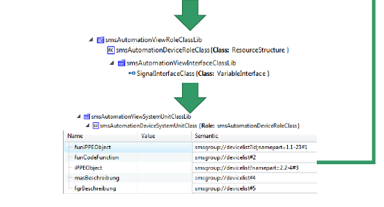
To support this transformation, AutomationML provides the concept of refSemantics (see Figure 7). They are added to AutomationML attributes and are a means for representing the mapping between the data format of the local domain tools and AutomationML. They can hold a reference to the data point within the data set of the local domain tool both on data source and data sink sides.
B. Challenge management
AutomationML provides means for the modelling of consistency rules [10]. For example, MathML or OCL formulae may be applied to map data points to each other and to represent their technical or natural dependencies. These consistency rules can be used for the integration of additional functions related to change management, white spot management, and consistency management. An example for the consistency management is the dependency between the size of a screw and the belonging nut. This dependency can be modelled with MathML.
C. Model generation
One of the main benefits of the application of AutomationML is the possibility of an incremental definition of the Type 2 and Type 1 models.
Following the described migration process, the development of the necessary role, interface and system unit class libraries can be executed incrementally as depicted in Figure 6. For each new local domain, new tool of a local domain, new data set, or new consistency rule (in Figure 6 named as new data exchange) the Type 2 AutomationML data model can be developed or updated and integrated into the overall Type 1 AutomationML model.
Clearly, the consistency of the data models has to be checked in each integration step. But this consistency is not a consistency at data instance layer rather than at conceptual layer. Similar concepts have to be mapped to each other which shall be a task of a dedicated data exchange specialist overseeing the complete engineering network.
Fig. 6 (model generation process) is available in the original PDF.
VI. Application Case
The presented architecture was developed and applied in the Christian Doppler Laboratory for Security and Quality Improvement in the Production Systems Lifecycle (CDL-SQI) and is supported by the INTEGRATE project [11]. One of the application cases reflected in the CDL-SQI is the engineering process of steel mills executed by one of the company partners in the CDL-SQI.
Within this engineering process, the local domains of overall system engineering, mechanical engineering, electrical engineering, fluidic engineering, and system simulation are interlinked. Currently, the application focuses on the data logistics towards the simulation as data sink.
The integration of the existing wide-ranging local ecosystem is one of the main challenges for the implementation of the transition from local to global domain. Often, csv files are used for data exchange. Based on these csv files, several engineering activities have been automated. Thus, these csv files cannot be replaced in the first migration step. To solve this problem dedicated csv2aml adapters were developed. These adapters exploit the possibility to refer to individual lines and columns expressed in csv files.
Within these adapters it is assumed that the individual lines of the csv files represent objects of the local engineering domain which follow the same concept. Accordingly, in the development of the Type 2 AutomationML model, the lines are conceptualized by appropriate role classes and system unit classes. The attributes of these role classes and system unit classes are equivalent to the information coded within the single columns of the csv files. To link the columns to attributes the refSemantic is applied giving the necessary pointer as shown in the lower part of Figure 7.
The implementation of the global domain is based on an aggregation of the Type 2 AutomationML files. For Type 1 AutomationML models, the main challenge was to handle the different hierarchies of the involved local domains as these hierarchies are partially incompatible.
As depicted in Figure 8, the solution of this problem is to replace the given hierarchy of the local domains with relations modelled by AutomationML interfaces and internal links in the model used in the global domain. Thereby, the Type 1 AutomationML model and especially its system unit class is not just an aggregation of the corresponding Type 2 models. Instead, the Type 2 hierarchies are replaced by additional interface classes used for hierarchy modelling.
Fig. 8 (hierarchy modelling in Type 1 AutomationML models) is available in the original PDF.
Beyond, the necessary consistency rules can be modelled as internal properties of the SystemUnitClasses modelling the data content of the concepts they are related to. These properties are added as MathML or OCL rules integrated in special attribute structures [10].
VII. Conclusions
Within this paper, we presented an AutomationML-based architecture for an engineering data logistic and a migration process towards an improved engineering data logistics. The architecture and process attend to the increasing importance of the engineering phase within the overall life cycle of production systems. It is intended to enable the improvement of quality and efficiency of engineering.
These architecture and migration process provide means to cope with major challenges and obstacles of engineering data exchange migration.
The obstacles of engineering habit, tool diversity, and economic meaningful migration are addressed by the distinction of local and global engineering domains and by the transformation of data between them. Here AutomationML enables a stepwise extension of the data logistic and a loose coupling of local and global domains.
The challenges of change management, white spot management, and consistency management are considered in the architecture within the global domain. Here, the necessary functions can be implemented based on the integrated data model.
In a first pilot, the architecture of the data logistic has been applied to a use case in the context of steel mill engineering. The evaluation of the use case showed the usefulness and the expected fast benefits with the developed architecture. Here, especially a generic csv-to-AutomationML transformer was successfully implemented and applied. This transformer replaces the implementation of tool interfaces with configuration of interfaces.
As future research and development activities we envision extending the developed implementations to more data formats of the data sources and sinks as well as to engineering domains including a generic methodology for mapping xml data to aml data. In addition, we plan to extend and explore the capabilities for change management, white spot management, and consistency management.
Acknowledgement
The financial support on the one hand by the Christian Doppler Research Association, the Austrian Federal Ministry for Digital and Economic Affairs and the National Foundation for Research, Technology and Development and on the other hand by the German Federal Ministry of Economic Affairs and Energy within the PAiCE program are gratefully acknowledged.
References
[1] Verein Deutscher Ingenieure: VDI Guideline 3695 – Engineering of industrial plants – Evaluation and optimization – Fundamentals and procedure, Beuth publisher, 2010 ff.
[2] R. S. Peres, M. Parreira-Rocha, A. D. Rocha, J. Barbosa, P. Leitão, J. Barata: Selection of a data exchange format for Industry 4.0 manufacturing systems, IECON 2016 – 42nd Annual Conference of the IEEE Industrial Electronics Society, Florence, 2016, pp. 5723–5728.
[3] S. Biffl, A. Lüder, D. Gerhard [Editors]: Multi-disciplinary engineering for cyber-physical production systems – data models and software solutions for handling complex engineering projects, Springer-Verlag, 2017, ISBN 978-3-319-56344-2.
[4] VDI/VDE: „Industrie 4.0 – Wertschöpfungsketten”, VDI/VDE Gesellschaft Mess- und Automatisierungstechnik, Status Report, April 2014.
[5] K. Hell: Methoden der projektübergreifenden Wiederverwendung im Anlagenentwurf, PhD Thesis, Otto-von-Guericke University, Magdeburg, Germany, March 2018.
[6] L. Hundt, A. Lüder: Development of a method for the implementation of interoperable tool chains applying mechatronical thinking – Use case engineering of logic control, 17th IEEE International Conference on Emerging Technologies and Factory Automation (ETFA 2012), Krakow, Poland, Sep. 2012.
[7] A. Calà, A. Lüder, J. Vollmar, M. Foehr: Evaluation of migration scenarios towards cyber-physical production systems using SysML, 2017 IEEE International Systems Engineering Symposium (ISSE), Vienna, Austria, Oct. 2017.
[8] M. Rother, “Toyota Kata”, McGraw Hill, New York, 2010.
[9] A. Lüder, N. Schmidt: AutomationML in a Nutshell, in B. Vogel-Heuser, T. Bauernhansl, M. ten Hompel (Hrsg.), Handbuch Industrie 4.0 – Produktion, Automatisierung und Logistik, Springer Verlag, Berlin, Heidelberg, December 2015.
[10] A. Lüder, J.-L. Pauly, M. Wimmer: Modelling consistency rules within production system engineering, 14th IEEE International Conference on Automation Science and Engineering (CASE 2018), Munich, Germany, August 2018, pp. 664–667.
[11] A. Lüder, J.-L. Pauly, R. Rosendahl, S. Biffl, F. Rinker: Support for engineering chain migration towards multi-disciplinary engineering chains, 14th IEEE International Conference on Automation Science and Engineering (CASE 2018), Munich, Germany, August 2018, pp. 671–674.
BibTeX
@inproceedings{lueder2018migration,
  author    = {L{\"u}der, Arndt and Pauly, Johanna-Lisa and Kirchheim, Konstantin and Rinker, Felix and Biffl, Stefan},
  title     = {Migration to {AutomationML} based Tool Chains -- incrementally overcoming Engineering Network Challenges},
  booktitle = {Proceedings of the 5th AutomationML User Conference},
  address   = {M{\"o}lndal, Sweden},
  month     = oct,
  year      = {2018},
  publisher = {AutomationML e.V.},
  url       = {https://www.automationml.org/conferences/conference-highlights/migration-to-automationml-based-tool-chains-incrementally-overcoming-engineering-network-challenges/}
}
How to Cite
A. Lüder, J.-L. Pauly, K. Kirchheim, F. Rinker, S. Biffl: “Migration to AutomationML based Tool Chains – incrementally overcoming Engineering Network Challenges”, Proceedings of the 5th AutomationML User Conference, Mölndal, Sweden, 24–25 October 2018.
This page is a text rendering of the original conference paper, published for accessibility and search. The PDF is the authoritative version. Figures 1, 2, 3, 5, 6 and 8 are available in the PDF. If you are an author and would like a correction, please contact office@automationml.org.