
Arndt Lüder and Nicole Schmidt (Otto-von-Guericke University Magdeburg)
Presented at
3rd AutomationML User Conference
7–8 October 2014, Blomberg, Germany
Hosted by Phoenix Contact
Type
Full paper, 9 pages
Open access
Republished by the AutomationML association. Copyright remains with the authors.
Abstract
Data exchange between engineering tools of production systems is a vital challenge also for small and medium size companies. These companies have limited capabilities to set up appropriate tool chains. In this paper a possible cooperation of two lobby groups are presented able to assist these companies in setting up advanced tool chains.
Motivation
The engineering of production systems is a complex process requiring the involvement of several engineering disciplines [1]. Each one of the involved disciplines has developed their own engineering tools optimized to the needs of the engineering activities to be executed by using these tools [2, 10]. Within German industry the opinion has been consolidated, that engineering tool chains are one of the key factors for future success. This becomes apparent looking at standards like the VDI guideline “Digital factory” [3, 4] or the requirements named in the recommendations for future work within the Industrie 4.0 initiative [5].
To ensure consistency and interoperability along the tool chain different approaches can be considered. They can be classified in three main classes following different philosophies to ensure interoperability: “one for all”, “Best of Breed”, and “Integration Framework”. The “one for all” philosophy follows the idea of a central tool or tool framework able to execute all necessary engineering activities and to handle all relevant engineering artefacts. The contrary philosophy is the “Best of Breed” philosophy. It postulates the application of several independent engineering tools which are loosely coupled by data exchange. In between both approaches the “Integration Framework” philosophy plays a mediator role. It applies a centralized data storage as data hub between the different engineering tools [6].
An extensive investigation based on a Delphi study with around 400 practitioners from different industries has shown that not all of these philosophies are equally relevant [7]. Figure 1 indicates that more than 60% of the engineers involved in detailed engineering of technical systems intend either a tool chain based on standardised data exchange formats or based on common project data bases.
Fig. 1 (distribution of engineering tool interface type expectations of practitioners) is available in the original PDF.
Within the development of appropriate data exchange technologies and their implementation the economical capabilities are not equally distributed. Most of the current developments are driven by larger companies like Daimler, VW, BASF, or Bayer to name only some. Such companies have a relevant market share to impact the activities of tool developers and standardisation organisations.
Another set of companies involved in engineering of production systems are small and medium size enterprises. They usually apply special skills and knowledge within the life cycle of production systems. This can be either the creation of special production system components like machines or the provision of special engineering activities. With their limited economical capabilities such companies are neither able to order specifically designed engineering tool interfaces nor to send staff permanently to standardisation organisations.
But what shall they do? In the following an alternative approach led by German VDMA and assisted by AutomationML is described and it will be highlighted how two lobby organisations can work together efficiently to improve the capabilities of small and medium size enterprises.
Current Activities
At first, it has to be considered which activities are currently ongoing considering the data exchange within the engineering of production systems and beyond.
As mentioned above, at the moment most popular is the Industrie 4.0 initiative. One aim of Industrie 4.0 is the integration of advanced IT capabilities like Internet of Things and Services, Cloud computing, and Big Data within industrial information processing on all layers of control. Thereby, the main interest is put on horizontal integration along value chain networks, vertical integration within networked production systems, and consistent digital engineering along the engineering chains all contributing to improve production system flexibility and adaptability. Following this aim the Industrie 4.0 platform (a joint activity of VDMA, ZVEI, and BITKOM) examines existing data exchange formats and their usability as a bundle to support both horizontal integration along value chain networks and consistent digital engineering.
In general the Industrie 4.0 initiative scrutinises a value creation chain covering the production system development and use (production system life cycle) but also the product life cycle as depicted in Figure 2. Thus here not only data exchange formats, developed for production system engineering, are relevant but formats for engineering and use of both production systems and products. And there are myriads mostly with special focus.
Fig. 2 (value creation chain) is available in the original PDF.
Some currently developed data exchange formats are STEP, ISO 15926, and AutomationML, relevant for the named life cycles and with larger coverage of data sets.
The STandard for the Exchange of Product model data (STEP) is an exchange data format standard family standardized within ISO 10303. It has been developed to model product related information ranging from product geometry over characterising properties up to production process descriptions for the processes required for product creation [9] within the product life cycle management (PLM). The STEP standard family provides different application profiles related to different fields of product engineering. Each of the profiles defines its own exchange data format but reflects consistency among the different formats. Some of the defined formats (especially the newer ones) are available as XML dialect.
ISO 15926 “Industrial automation systems and integration — Integration of life-cycle data for process plants including oil and gas production facilities” has been developed as a kind of lingua franca for the engineering of process plants [11]. It provides capabilities for a semantic mapping of data objects between different engineering tools exploiting standardised dictionaries.
In contrast to both approaches (STEP and ISO 15926) which have an explicit semantic representation, AutomationML has an implicit semantic representation.
The AutomationML data format, developed by AutomationML e.V., is an open, neutral, XML-based, and free data exchange format which enables a domain and company spanning transfer of engineering data of production systems in a heterogeneous engineering tool landscape. The goal of AutomationML is to interconnect engineering tools in their different disciplines, e.g. plant planning, mechanical engineering, electrical engineering, process engineering, process control engineering, HMI development, PLC programming, robot programming, etc.
AutomationML stores engineering information following the object oriented paradigm and allows modelling of physical and logical plant components as data objects encapsulating different aspects. An object may consist of other sub-objects, and may itself be part of a larger composition or aggregation. Typical objects in plant automation comprise information on structure, geometry, kinematics and logic, whereas logic comprises sequencing, behaviour and control descriptions.
In addition, AutomationML follows a modular structure by integrating and enhancing/adapting different already existing XML-based data formats combined under one roof, the so called top level format (see Figure 3). These data formats are used on an “as-is” basis within their own specifications and are not branched but restricted for AutomationML needs. Logically AutomationML is partitioned in:
- description of the plant structure and communication systems expressed as a hierarchy of AutomationML objects and described by means of CAEX following IEC 62424,
- description of geometry and kinematics of the different AutomationML objects represented by means of COLLADA 1.4.1 and 1.5.0 (ISO/PAS 17506:2012),
- description of control related logic data of the different AutomationML objects represented by means of PLCopen XML 2.0 and 2.0.1, and
- description of relations among AutomationML objects and references to information that is stored in documents outside the top level format.
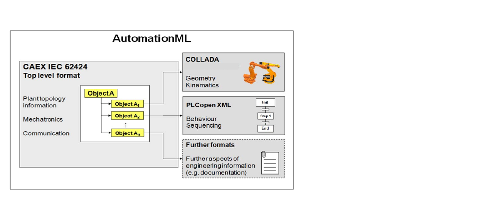
The foundation of AutomationML is the application of CAEX as top level format and the definition of an appropriate CAEX profile fulfilling all relevant needs of AutomationML to model engineering information of production systems, to integrate the three named data formats CAEX, COLLADA, and PLCopen XML, and to enable an extension if necessary in the future.
CAEX enables an object oriented approach (see Figure 4) where
- semantics of system objects can be specified by using roles defined and stored in role class libraries,
- interfaces between system objects can be specified by using interface classes defined and collected in interface class libraries,
- classes of system objects can be specified by using system unit classes (SUC) defined and summarised in system unit class libraries, and
- the individual objects are modelled in an instance hierarchy (IH) as a hierarchy of internal elements (IE) referencing system unit classes they are derived from and role classes defining their semantics and containing interface objects used to interlink objects among each other or with externally modelled information (e.g. COLLADA and PLCopen XML files).
Fig. 4 (AutomationML architecture) is available in the original PDF.
The VDMA Approach
By conducting a member survey the VDMA working group control has identified that engineering tool interaction is a critical issue for small and medium size enterprises in 2012. Thus, VDMA has launched a working group responsible for tackling this problem. Therefore, the working group integrated practitioners from production system engineering, tool vendors, and academia to consensually
- identify the tool chain of interest,
- develop a common data model for all data to be exchanged between tools and which are relevant in an engineering project, and
- specify a data representation within a data exchange format.
Starting in 2012 the necessary tool chain has been chosen very fast. As small and medium size enterprises usually have only a limited number of engineers working within the development departments which again have to focus on a limited number of tools, the tool chain has been limited to mechanical engineering, electrical engineering, and control engineering as depicted in Figure 5.

Nevertheless, the working group agreed on the need to enable the exchange of information beyond the three identified tool types. It shall be possible, that further tools can read and write the related data.
The VDMA Data Model
After having the tool chain identified the working group had discussed and developed a common data model for all data to be exchanged. Starting point for this identification comprised the following considerations:
- the information concepts to be modelled shall cover the minimal necessary set of information relevant to reach significant gains,
- the modelled information shall cover the common concepts relevant within at least two engineering tools,
- the modelled information shall enable the referencing of external information, and
- the modelled information shall also cover project management and tool management information.
As a result a data model consisting of six main concepts has been developed as given in Figure 6. This data model covers the concepts project, sub-project, function unit, device, device function, and software tag.

The concept project covers the complete project information with all necessary project related parameters and properties like project number, name, version, and revision. In addition, it covers relevant tool related information enabling the correct interpretation of the project information. The concept sub-project enables the segmentation of a project to interrelated sub-projects covering different disciplines, components, etc.
The concept function unit is related to a part of the designed production system (or production system component like machine) providing one or more dedicated manufacturing functions. Examples of such functions can be a drive chain providing a motion function as well as a diagnosis function. To delineate the function unit relevant describing parameters like name, identifier and user related parameters need to be exchanged. In addition, it may comprise expected sequence of steps to be executed as well as relevant drawings and description files.
Function units consist of a set of devices implementing the functions of the function unit. The concept device covers these devices like drive, gearbox, and controller in the drive chain. To describe such a device the device vendor, its order and part numbers, and device parameters are relevant. In addition, there are data sheets and documentation files which need to be referenced.
Within the different involved disciplines the devices provide device functions, resulting in the next concept to be covered. Such device functions have identification information and information related to the mechanical, electrical, and control software engineering.
The last concept is the software tag. It represents the physical I/O of devices which finally will be connected within the wiring of the production system. The describing properties for such a software tag contain for example the address and the unique identifier.
A Possible XML Representation Exploiting AutomationML
To reach an applicable XML based representation of the data model a new schema can be defined. This schema will contain the definition of one XML tag for each of the six concepts and subtags or attributes for each of the describing properties.
This possible approach will have two main challenges. At first, it defines just another interface to be implemented by tool vendors. In most cases they also have to implement AutomationML based interfaces forced by larger companies following their tool chain implementation programs. At second, it limits the adaptability of the data model. If additional information will be integrated in the data model the complete schema has to be updated with all version and revision problems within the data format itself as well as in the implementation of appropriate tool interfaces.
To avoid such problems a possible solution could be the adaptation of already existing or currently implemented tool interfaces. As there are several AutomationML interfaces for tools under consideration and AutomationML is a generic data format adaptable to different application cases, AutomationML can be an appropriate candidate for the implementation of a VDMA interface. The modelling of the VDMA data format by AutomationML means seems to be an appropriate and effort reducing approach.
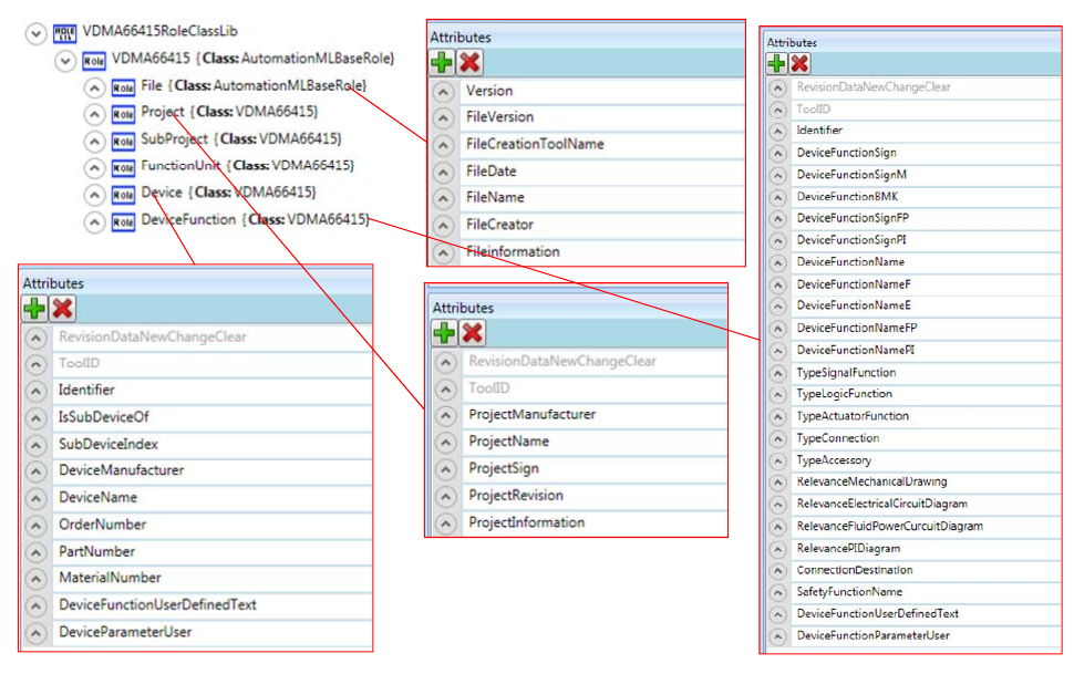
Appropriate role and interface classes are the starting point of an AutomationML representation. Naturally, each of the named concepts has to be represented by a role class. The only exception is the software tag which is represented by an interface. Figure 7 depicts the resulting role class library. The basic role class VDMA66415 contains all attributes relevant for all concepts named above like the tool identification. All other role classes (for the concepts project, sub-project, function unit, device, and device function) are derived from this role and are enriched by relevant attributes. As additional role class File is integrated covering the data exchange unit and its special properties defined by VDMA.
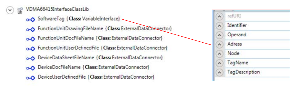
To model the software tag an interface class is used. It is derived from the variable interface class which is already defined in Part 4 of the AutomationML whitepapers. Thereby, the compatibility to logic modelling in AutomationML is preserved. In addition capabilities to reference external information for function units and devices are required which are also modelled by interfaces derived from external data connectors. The resulting interface class library is given in Figure 8.
To apply the developed role classes and interface classes a system unit class library has to be developed for each application case. The left part of Figure 9 gives an example. For each concept named above a system unit class is defined with an appropriate supported role class. In Figure 9 the system unit classes are named equally to the role classes. But this is not necessary. Each of the system unit classes has to contain all of the relevant attributes defined in the role classes as well as the necessary interfaces to reference external information.
Then, those system unit classes can be instantiated as internal elements in the instance hierarchy as given in the right part of Figure 9.
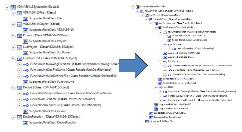
The defined structure maps all information modelled in the VDMA data model to AutomationML modelling elements. In contrast to a schema based modelling of the data model the AutomationML version has three main benefits:
- In case of changes in the VDMA data model only the related role classes and interface classes have to be updated. It is not necessary to change the implementation of the tool interfaces.
- Tool vendors only have to develop one interface which will be adapted to different application cases. This will reduce software implementation costs and can enable small and medium size companies to get an appropriate interface early and at fewer costs.
- Tool users can apply additional AutomationML based features for data exchange like eCl@ss integration or OPC UA integration in the future, if their application cases call for it.
Discussion and Conclusion
Within this paper a possible combination of developments of VDMA and AutomationML was represented which had been developed by the authors in cooperation with the members of the AutomationML association and the relevant VDMA working group. It shows how especially small and medium size enterprises can benefit from such an approach.
The presented structures and relations are on an intermediate stage. The final representation of the VDMA data model is in the scope of the relevant working group of the VDMA. It is not finalized yet and may change during the ongoing work.
References
[1] A. Lüder, M. Foehr, L. Hundt, M. Hoffmann, Y. Langer, St. Frank: Aggregation of engineering processes regarding the mechatronic approach, 16th IEEE International Conference on Emerging Technologies and Factory Automation (ETFA 2011), Toulouse, France, September 2011.
[2] H. Wörn, D. Frey, J. Keitel: Digital factory – Planning and running enterprises of the future, Proceedings of the 26th Annual Conference of the IEEE Electronics Society IECON-2000, pp. 1286–1291.
[3] Verein Deutscher Ingenieure: VDI Richtlinie 4499-1: Digitale Fabrik – Grundlagen, Düsseldorf 2008.
[4] Verein Deutscher Ingenieure: VDI-Richtlinie 4499 – Digitale Fabrik – Blatt 2, Düsseldorf, 2009.
[5] H. Kagermann, W. Wahlster, J. Helbig (Eds.): Umsetzungsempfehlungen für das Zukunftsprojekt Industrie 4.0 – Deutschlands Zukunft als Industriestandort sichern, Forschungsunion Wirtschaft und Wissenschaft, Arbeitskreis Industrie 4.0, 2013.
[6] L. Hundt, A. Lüder: Development of a method for the implementation of interoperable tool chains applying mechatronical thinking – Use case engineering of logic control, 17th IEEE International Conference on Emerging Technologies and Factory Automation (ETFA 2012), Krakow, Poland, September 2012.
[7] A. Lüder, N. Schmidt, S. Biffl, H. Steininger: Analyzing Requirements on Software Tools According to the Functional Engineering Phase in the Technical Systems Engineering Process, 19th IEEE International Conference on Emerging Technologies and Factory Automation (ETFA 2014), Barcelona, Spain, September 2014.
[8] GMA Fachausschuss 7.21 “Industrie 4.0”: Statusreport Industrie 4.0 – Wertschöpfungsketten, April 2014.
[9] X. Xu, A. Nee: Advanced Design and Manufacturing Based on STEP, Springer Publisher, 2009.
[10] R. Drath, A. Fay, M. Barth: Interoperabilität von Engineering-Werkzeugen, at – Automatisierungstechnik 59 (2011), Issue 7, pp. 451–460.
[11] FiaTech Report: An Introduction to ISO 15926, November 2011.
BibTeX
@inproceedings{lueder2014minimal,
  author    = {L{\"u}der, Arndt and Schmidt, Nicole},
  title     = {A minimal tool interface for machinery and equipment engineering},
  booktitle = {Proceedings of the 3rd AutomationML User Conference},
  address   = {Blomberg, Germany},
  month     = oct,
  year      = {2014},
  publisher = {AutomationML e.V.},
  url       = {https://www.automationml.org/conferences/conference-highlights/a-minimal-tool-interface-for-machinery-and-equipment-engineering/}
}
How to Cite
A. Lüder, N. Schmidt: “A minimal tool interface for machinery and equipment engineering”, Proceedings of the 3rd AutomationML User Conference, Blomberg, Germany, 7–8 October 2014.
This page is a text rendering of the original conference paper, published for accessibility and search. The PDF is the authoritative version. Figures 1, 2 and 4 are available in the PDF. If you are an author and would like a correction, please contact office@automationml.org.