
Rainer Drath (Faculty of Technology, Pforzheim University of Applied Sciences) · Idar Ingebrigtsen (Simplification, Standardisation and Industrialisation Department, Equinor ASA, Oslo)
Presented at
5th AutomationML User Conference
24–25 October 2018, Mölndal/Gothenburg, Sweden
Hosted by ABB
Type
Full paper, 8 pages
Open access
Republished by the AutomationML association. Copyright remains with the authors.
Abstract
This paper describes a concept for an electronic data exchange of System Control Diagrams (SCDs) from the process engineering to control engineering domain allowing automatic generation of automation code in the control engineering. SCDs are standardized by the Norwegian NORSOK organisation and contain, in contrast to P&IDs, concrete function blocks and their interrelations, a real representation of the actual control application. SCDs are of interdisciplinary nature containing process and automation information at the same diagram. Their application in the Norwegian oil and gas industry is well established and of high value for the automation departments and control room operators. Seamless electronic data exchange is however not established today, the printed diagram is still the main input for the control system supplier’s engineers. This paper investigates a way to utilize AutomationML to overcome this issue.
Keywords: AutomationML; P&ID; SCD; IEC PAS 63131; Function Blocks; XML
I. Introduction
The engineering of process plants is usually carried out in interdisciplinary teams using various software tools [1]. An essential and internationally established document in this planning is the piping and instrumentation diagram (P&ID). The P&ID is the central document in which information on process engineering, piping technology and process control technology is brought together. In many discussions and planning steps it forms the basis for information and coordination of the various trades. Especially of interest in the P&ID, beside tanks, pumps and pipes, is the process control engineering request (PCE request) that is represented by the instrumentation and main control functions, graphical elements that models key information relevant to the automation engineering team. It is a special interdisciplinary elements on the P&ID, designed by process engineers, modelling the requested main automation functions in the process and their connection to the process equipment. A PCE request is abstract and usually does not define the concrete technical implementation of the requested functions.
The P&ID, once handed over to the automation team, is evaluated with focus on the PCE requests. Finally, the automation engineering team develops automation functions to fulfill the PCE requests, but the technical implementation usually remains competitive and vendor specific.
To interpret PCE requests across interdisciplinary teams, the graphical notation of the PCE request is matter of different standards, e.g. IEC 62424 [2][3]. In modern workflows, PCE requests are exported as proprietary files, e.g. as Excel sheets. The standardization community currently works on detailed standardization of electronic models of the PCE request, e.g. the NAMUR container according to NE150 [4][5].
Widely hidden and not in the spot of the international standardization community, the national Oil&Gas industry of Norway has developed and introduced a new type of diagram, targeting the better modeling of automation relevant information connected to the P&ID: the system control diagrams (SCD). An SCD is not a replacement of a P&ID, but really a logic diagram made to cover the control application of the Process Control and Process safety functions in detail. It can be regarded as the next step in control system design after the making of the P&IDs. It is based on the information developed through P&ID design, but it also includes input from other discipline design, such as Safety, Mechanical and Electrical. SCDs are standardized as IEC PAS 63131 [6].
The 63131 standard provides a set of standardized function blocks. But similar to the state of the art in the P&ID world, the electronic data exchange of those function blocks across the engineering workflow is a bottleneck due to a lack of an electronic information model. The function blocks, annotated in the SCDs, are either manually interpreted by the automation teams, or treated by proprietary software solutions that vary from project to project.
To overcome this issue, a generic way to electronically model the function blocks in the SCDs is needed. The authors initiated a research initiative in order to investigate the capabilities of AutomationML for the given purpose. The present paper first time describes a generic methodology to model the 63131 standard. The result is a general and re-usable methodology which will be proposed to become a normative part of the IEC 63131 standard.
Section II gives an overview about SCDs and describes the state of the art. Section III proposes a modelling concept based on AutomationML including examples. Finally, section IV gives an outlook and summarizes the findings.
II. Related Work
A. A brief overview about SCDs
The history of logic diagrams for control systems goes back into the late 70s and the early 80s. The process control logic design was designed using elementary function blocks only. Simple logic diagrams were then made for the main part of the process. In the early 90s, more control and operational functionality and more uniformity in the control application have been desired. It has been experienced that the control applications become too varied and directly not understandable for later maintenance. Norsk Hydro did Oseberg field development in 1985–1989 much based on control narratives only and the need for improved documentation became clear after experiencing how creative engineers will solve similar tasks in many different ways. More standardization was needed. At the same time Statoil introduced higher level functions blocks in 1990, type of blocks that later have been defined as Application blocks.
The former Norsk Hydro Oil and Gas (merged with Statoil in 2007) started to develop the SCD concept in 1991 and it was first time used on the Brage project. Next out was Conoco (today ConocoPhillips) to use it on the HEIDRUN project in 1995. In 1996 the work started to make it a standard within the Norwegian O&G business. In 1999 the rev.1 of the NORSOK I-005 standard was issued. Since 2018, Statoil ASA is named Equinor ASA.
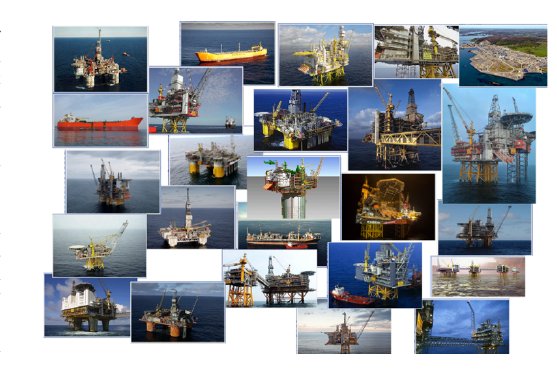
From 1995, on 29 Equinor installations the ICSS control application design have been done in accordance with NORSOK I-005 (now issued as IEC PAS 63131). Nearly all other installation build for the Norwegian Continental Shelf in the same period by other operators have used it as well. This gives the Norwegian Oil and Gas business over 20 year’s experience with this standard. Fig. 1 illustrates the 29 industrial Oil&Gas Equinor platforms that have been engineered based on the 63131 standard.
The 63131 standard describes a method of designing control system logic. The standard actually consists of two parts. The first part defines a set of control function templates (function blocks), the second part defines a diagram type used to show the interconnection of the control functions templates.
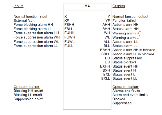
16 different templates for logical function blocks are defined. Fig. 2 gives an example of a function template. The usage of vendor specific function blocks is allowed but rarely used. Internal Equinor statistics from the ongoing Johan Sverdrup mega project show that 99% of the control application is covered by the 16 predefined function from IEC PAS 63131. Additionally, it defines a number of elementary function blocks as AND, OR or SPLIT OF SIGNAL. See Fig. 5.
The SCDs are relatively easy to learn and read. In that way it makes the process control logic available for others than the programmers themselves. The function blocks are on a functional and operational high level. Tag numbers on SCD corresponds to the object names on the operator station objects. They are ’the point of access’ for operators. The diagram presents the control logic on a process-diagram, including the safety interlocks. It gives an easy overview of interlock logic during trouble shooting. Fig. 3 gives an idea about an SCD: the blue color illustrates the process, magenta color represents the process safety system logic, black color is the process control system logic. Additionally, there are some green signals lines, these are interface signals between the process control and process safety system.
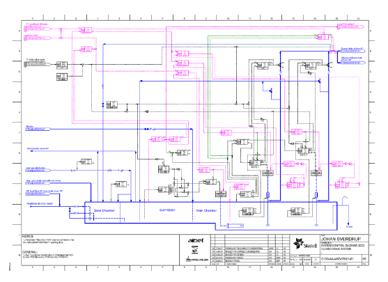
The importance of the SCD concept can be illustrated by the Johan Sverdrup oil platform: a giant platform for one of the largest oil fields at the Norwegian continental shelf, requiring the total of 51.000 Norwegian man years to develop and construct. 598 SCDs have been developed by 4 contractors as configuration basis for more than 120 nodes and 500 cabinets.
B. Electronic data exchange in systems engineering
The engineering of industrial plants in process or manufacturing industry including Oil&Gas platforms is characterized by the separation of the overall workflow in multiple engineering phases as mechanical construction, process engineering, electrical engineering, automation engineering etc. The different domains perform multiple activities and require different specialized engineers of different education using individual software tools. The overall workflow forms a value creation chain, and all activities typically base on input from other activities and deliver output for other activities.
Today, seamless data exchange between engineering tools becomes more and more a bottleneck in engineering efficiency. This statement is valid for all industries with complex and automated plants. The handover of engineering data from one activity to the next, from one tool to another tool is identified to be a key cost driver in engineering. In many cases, it is done manually or via proprietary solutions. While an integrated tool suite, combining all used tools in top of a common database, would elegantly solve this issue, most of the used engineering tools are from different vendors and are not designed to interact with one another. The approach to perform data exchange via proprietary files results to an explosion of required exporters and importers with high version and maintenance effort.
Both approaches are unsatisfactory [8][9]. But globalization and digitalization trends [10] require digital solutions to bridge the gaps [11]. How do other industries solve this problem?
- The chemical and pharmaceutical industry delivers a very common example for the lack of data exchange: the handover of P&I diagrams between the process engineering and the control engineering phase. Up to now, no comprehensive electronic data model has been established. With IEC 62424 and the data format CAEX (Computer Aided Engineering Exchange), an electronic data model of the PCE request has been standardized in 2006. CAEX itself is a meta model allowing to model any classes, it does not predefine domain specific libraries. With the IEC 62424, CAEX is utilized in order to model the PCE request. A more comprehensive approach to model PCE requests has been developed by the GMA 6.16 with the NAMUR container [5][9][12]. Further approaches to standardize the data exchange between process and control engineering are NE100 [13], STEP [14], ISO 19526 [15], Dexpi [16], Pandix [17] and many more, but with no focus on SCDs.
- The discrete industry delivers another typical example for the lack of data exchange. Among other scenarios, the handover of geometry or kinematics data is identified in 2005 [18] to be a key cost driver in engineering which takes about 50% of the overall cost of an automation system. This is why Daimler initiated 2006 the development of AutomationML [19][20].
- For the Oil&Gas industry, the data exchange of SCDs between the engineering contractor and ICSS supplier is, until today, unsolved. Due to the promising flexibility of AutomationML, the question is: can AutomationML model the function blocks according to the given general requirements described in III.A?
C. CAEX
CAEX is an XML based file format standardized in IEC 62424. It provides a generic object oriented modelling approach allowing to model libraries of object classes, and the modelling of an instance hierarchy. Hence, it provides means to model both, types and individual instances. It is not bound to any industry.
Whereas IEC 62424 has originally been initiated to define the graphical representation of PCE requests in the process industry, the definition of the CAEX data format has been added in order to provide an electronic information model for the PCE request on top of its graphical representation. Hence, the CAEX model of the PCE request was the first time of digitalizing a standard.
D. AutomationML
AutomationML [19][20][21] is a free and neutral file format, initiated 2006 by the Daimler AG in the manufacturing industry. It aims for modelling various engineering information of different domains. It is standardized in the IEC 62714 [20]. For different types of information, it re-uses existing and well established data formats and only standardizes their application and their interlinking. The plant topology is described through CAEX according to IEC 62424, Kinematics and geometry through COLLADA [22] and behaviors through PLCopen [23].
Since AutomationML has adopted CAEX as the base format, it inherits its flexibility: it allows to model domain specific libraries, and is not bound to any special industry. Two key properties of AutomationML are substantial in its application in a heterogeneous tool landscape:
- The modelling of mixed semantics – this means that standard classes and proprietary classes are modelled in the same way, and can be stored together in the same AutomationML file. This allows to standardize where needed and still model and transport proprietary data that can only be interpreted by prepared target tools.
- The labelling of AutomationML files – this means that every AutomationML file gets a meta information block containing information about the source of the file. This allows any receiver to distinguish AutomationML files from different tools and to identify the needed semantics or dialect.
Meanwhile, AutomationML has reached industrial application in a wide range of applications, e.g. in virtual commissioning [24], in data synchronization across multiple engineering tool platforms [25][26], in the modelling of communication networks [27][28], in the extended modelling of PCE requests [5][8][9] or in the evaluation of openness of engineering tools [29].
E. Electronic models of SCDs
There is currently no electronic data format for SCDs available, but the community around the 63131 standard aims for achieving electronic data exchange instead of exchanging printed diagrams or proprietary files.
III. Proposal for Modelling 63131 Function Blocks with AutomationML
A. General requirements
The modelling of the 63131 function blocks should fulfill the following general requirements:
- The data model should allow modelling 63131 standard function blocks and user defined function blocks.
- The data model should allow modeling both function block types and SCDs with function block instances, and connections between function blocks, and between SCDs.
- The data model should be extensible for future purposes and should allow to identify standard data and extensions.
- The data should allow black box modelling of function blocks with no internals in order to be vendor independent.
B. General modelling strategy
Since the 63131 function blocks are standardized, their inner logics is known and usually proprietary and individually implemented by target automation engineering tools. Therefore, the inner logics can be excluded from electronic data exchange, a blackbox modelling of function blocks is sufficient. This general modelling decision simplifies the model, makes the overall approach more robust and allows for vendor specific implementations of the function blocks. Hence, no PLCopen XML modelling of the logics is required, instead, all modelling is covered by the object modelling capabilities based in CAEX.
The key focus of the modelling is in the function block library defined in the 63131 standard function blocks, however the modelling of elementary function blocks is required, as well as the modelling of user defined function blocks. Finally, a modelling strategy is required for unknown function blocks.
C. 63131 function block library
The 63131 standard comprises a set of 16 function block types, see Table 1. Each function block has input and output signals of certain types. Since AutomationML supports object oriented modelling of classes, the authors created a new CAEX SystemUnitClassLibrary and a generic CAEX SystemUnitClass NorsokFunctionBlockClass. All further 63131 function blocks are derived from this class. Then, for each required function block, a new SystemUnitClass are created: MA, CA, HA, SBV, SB, CS, HB, LB, MB, OA, QA, SBB, SBC and SBE.
Table 1: AB – Application blocks acc. to 63131
| Abbreviation | Designation |
|---|---|
| CA | PID Controller |
| CS | Step Controller |
| HA | Manual analogue input |
| HB | Manual binary input |
| KB | Sequence header |
| LB | Shutdown level |
| MA | Analogue measurement |
| MAS | Analogue measurement from subsystem |
| MB | Binary input |
| OA | Analogue output |
| QA | Totalizer |
| SB | Binary output |
| SBB | Breaker operation |
| SBC | Coordination of multiple SBE |
| SBE | Electrical equipment binary operation |
| SBV | Pneumatic/Hydraulic equipment binary operation |
In the last step, common input and output signals are predefined. Those signals are not fixed, supported by AutomationML principles they may be augmented or reduced at the instance level. The used signals are defined in as signal class library described in section G of this paper. Fig. 4 gives an impression about the function block library: a subset of all function blocks, neutrally modelled in CAEX.
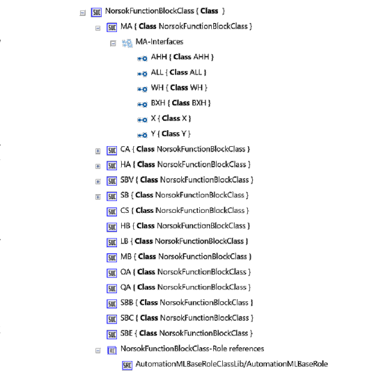
In the result, the authors achieved a neutral AutomationML file containing a neutral class library with neutral 63131 standard function block classes. This file is the MASTER library, it is re-usable and distributable for all data exchange scenarios. Further classes will be added as described in the following sections.
The 63131 library may change in future, but the general methodology for modelling function blocks in AutomationML is generic. However, similar to the CAEX library for PCE requests, the presented approach is considered as a digitalized 63131 standard to be reused across all SCD exchange partners. Hence, the authors propose to standardize this library and to make it a normative part requested for all SCD related data exchange.
D. Elementary function block type library
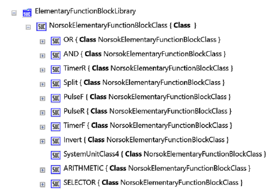
In order to model glue logic in SCDs, elementary function blocks as OR, AND, Split or Timer are needed. The general methodology for modelling them is identical to the 63131 function block classes.
Table 2: EFB – Elementary function block acc. to 63131 I-005
| Notation | Designation | Function |
|---|---|---|
| O | Logic “OR” | X1 or X2 = Y |
| & | Logic “AND” | X1 and X2 = Y |
| ≠ | Logical “XOR” | Exclusive X1 or X2, Y = 1 |
| H | High selector | Y = the higher of X1 and X2 |
| L | Low selector | Y = the lower of X1 and X2 |
| > | Comparator high | Y = 1 when X1 > X2, o/w Y = 0 |
| < | Comparator low | Y = 1 when X1 < X2, o/w Y = 0 |
| + | Arithmetic plus | X1 + X2 = Y |
| − | Arithmetic minus | X1 − X2 = Y |
| * | Arithmetic multiply | X1 * X2 = Y |
| / | Arithmetic division | X1 / X2 = Y |
| M | Memory element | S = Set, R = Reset |
| S | Split of signal | — |
| # | Operational formula | Users choice |
| A | Analogue select | Y = X1 when S = 0, Y = X2 when S = 1 |
Fig. 5 shows a subset of elementary function block types, the modelling of further classes follows the same rules as described.
E. Vendor specific function block type library
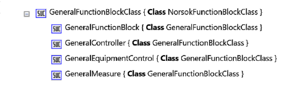
AutomationML allows modelling user defined vendor specific function blocks that are not part of the 63131 standard. The modelling methodology is identical to previous classes. A potential use case for the industrial application of this method is to import function block libraries from different automation vendors in order to use them in the interdisciplinary SCD engineering process. Using those libraries significantly simplifies the mapping of SCD data to target specific tools. Fig. 6 give an example of a user defined function block library.
F. SCD related libraries
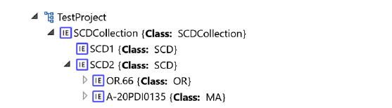
For the general organization of SCDs, two base classes have been introduced: the SCD and SCDCollection class, see Fig. 7. They allow to model the SCDs.

Fig. 8 shows how the SCD classes are used: SCDs are collected in an SCD Collection element. This collection depicts 1:1 the diagram view of SCD source tools. Multiple SCDs and their internal content can be modelled this way.
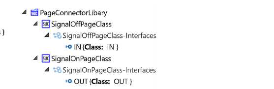
Since SCDs can be connected with one another, another organizational library is requested to model page connectors. Page connectors are not part of the 63131 standard, but for practical reasons, they are required to indicate that a signal is continued on another SCD page. From the perspective of the electronic data model, this approach seems to be outdated and a contribute to the old diagram oriented way of engineering. Target control engineering tools will indeed ignore those page connectors. But for the sake of completeness and archiving purposes, they are useful. Fig. 9 shows the input and output connector classes for SCD pages.
G. Signal type library
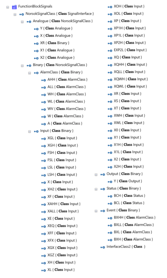
The modelling of signals is possible in different ways: e.g. one interface class whereas all different types (input, output, digital, analogue etc.) are modelled by means of parameters, or by modelling every possible signal type in an own class. The authors decided to model all signal types explicitly without descriptive parameters.
The parent signal is the NorsokSignalClass, derived from the AutomationML standard signal interface class SignalInterface. Then, further generic interface classes Analogue, Binary are derived from NorsokSignalClass. Based on the described classification, all detail signal interfaces are derived. Fig. 10 shows the AutomationML interface class library.
H. Strategy to manage unknown data
An interesting aspect of the resulting AutomationML export file is its ability to hold unknown information. Whenever the source tool specific exporter detects an object type that is not existing in the predefined AutomationML class library, it creates a new class in the AutomationML library and instantiates this. The authors gave those classes a prefix “dummy” in order to illustrate the effect. In the result, the AutomationML file does not skip information, it holds a mix of known and unknown classes and instances. This is a special ability of AutomationML and will be further used in the data exchange to the target control engineering tool. Fig. 11 shows the AutomationML structures in the AutomationML Editor [21].
The target control engineering tool is interpreting the AutomationML file. Known objects are identified by their class reference and are mapped to target tool specific function blocks, signals and links. Unknown objects are identified and copied into a separate AutomationML file that contains all unknown classes.
Finally, the unknown objects do not hinder the import, they are taken aside, whereas known blocks are imported. The library of unknown objects is an electronic data model of unknown things and represents a suited software requirement specification to start a formal software development process for the missing function blocks on the target side, or to start a discussion with the source tool team to figure out the meaning of those.
Fig. 11 (the resulting AutomationML file visualized with the AutomationML Editor) and Fig. 12 (the resulting library of unknown classes) are available in the original PDF.
I. Overall workflow
The overall workflow comprises the following steps:
- The source engineering exporter loads the predefined master AutomationML library file. It saves a copy of and creates an empty CAEX InstanceHierarchy.
- The source engineering exporter creates an InternalElement SCDs and searches for all SCDs in the source engineering tool. It identifies the SCDs and for each source SCD, it creates a child InternalElement of type SCD representing the current SCD in the source engineering tool.
- The exporter runs through all source SCDs.
- The exporter identifies all objects of the current SCD and searches for counterparts in the master AutomationML library. If an object type is found, it is instantiated in the CAEX InternalElement SCD. If the type is not found, the exporter creates a new dummy class in the CAEX library and instantiates this dummy class in the SCD element.
- After having exported all elements on the SCD, the exporter continues with the next SCD.
- After having exported all SCDs with their elements, the exporter runs through all connections in the SCDs and creates InternalLinks or PageConnectors. It is important to do this step after having exported all elements of all SCDs, otherwise the connectors possibly have no counterpart in the AutomationML model.
- The AutomationML export file is saved and submitted to the target engineering tool.
- The importer of the target engineering tool opens the AutomationML file and searches for the InstanceHierarchy. It finds the SCD collection object and the contained SCDs.
- The importer runs through all InternalElements of each SCD and searches for counterparts in the target engineering tools type library. For each identified object it creates an object instance (function block) in the target tool. For each unknown object it submits the type into a new library UnknownLibrary within a separate AutomationML file.
J. Example
The presented approach has been prototypically tested by the authors together with the engineering supplier Aker Solutions and the automation provider Kongsberg Maritime by means of a real project.
The selected example SCD is shown in Fig. 13 and contains more than 200 objects, 800 signals and around 200 connections. The source data is Aker Solutions Comos Oil & Gas, as tool example the authors used the Aker Solutions COMOS version.
The resulting AutomationML file has been generated out of the COMOS tool and submitted to the target engineering tool, the Kongsberg Maritime AIM-2000. Fig. 14 shows the result: the visualization of the mentioned 200 objects including the unknown types.
Fig. 13 (example SCD with more than 200 objects, Aker Solutions) and Fig. 14 (target tool visualization, Kongsberg Maritime) are available in the original PDF.
IV. Conclusion and Outlook
This paper first time investigates the application of AutomationML in the electronic data exchange of SCDs according to the 63131 standard, prototypically developed and tested by means of real diagrams. As result, it has been proven that AutomationML is able to fulfill the requirements defined in III.A – the AutomationML format is able to model required information. The method how to model 63131 standard function blocks in AutomationML has been proven, elementary and generic function blocks have been added, and an alarm and signal library has been created. Together with Aker Solutions and Kongsberg Maritime, the authors developed and tested the concept by a prototypic COMOS-to-AutomationML-exporter on the source side, and an importer for the Kongsberg AIM 2000 on the target side. The overall feasibility by means of a realistic example SCD has been successfully tested.
The present work is a further step in the digital transformation of the engineering of production systems. As the SCD is on a level that there is a 1:1 relation with the function blocks that should be in the control system, the automation supplier can automatically generate more or less the complete control application when he gets the information in digital format. This will potentially save a significant amount of hours. Additionally, the proposed concept has the potential to reduce the time used on the factory acceptance tests (FAT) to yellowline the implemented logic versus the SCDs. As the SCD standard have been lifted from PAS 63131 to IEC standard, the authors will propose this AutomationML content definition into the SCD IEC standard IEC 63131. In that way we can expect that this methods will be known to the contractors and ICSS/DCS suppliers internationally and we can include it in future contracts.
Beside the present digitalization of a so far unsolved data exchange problem, the scientific value of the present method is in a variety of potential future applications, possibly executable as software service in the cloud. Since the logic information is now available in an electronic machine readable object model, the AutomationML files for SCDs could be investigated by algorithms/apps for inconsistencies, errors, re-usable patterns, etc. Those apps could also automatically solve errors based on rules. The AutomationML files for SCDs could be used for archiving purposes, e.g. together with a PDF as graphical visualization. The AutomationML files could be used to calculate and visualize differences between SCD versions and to check those changes against rules in order to validate their impact (interesting for the sender and the receivers side). The AutomationML files could be a base for a workflow support tool providing difference management between multiple senders and receivers, e.g. as described in [8] and [25]. Artificial Intelligence could be an interesting technology approach to be applied based on big data to automatically learn data, perform e.g. automatic linking, IO allocation, parameterization, or finding inconsistencies in the linking and parameterization.
Observing the sequence of ETFA papers about AutomationML since 2011, this paper forms a significant milestone in the transfer of AutomationML methods and concepts into new industrial applications.
References
[1] Fay A., Efficient engineering of complex automation systems, In: Schnieder (editor): Will traffic automatically be safer?, Braunschweig, 2009, pp. 43–60 (in German language).
[2] IEC 62424:2008: Representation of process control engineering – Request in P&I diagrams and data exchange between P&ID tools and PCE-CAE tools. 2008.
[3] IEC 62424:2016: Representation of process control engineering – Request in P&I diagrams and data exchange between P&ID tools and PCE-CAE tools. 2016.
[4] NE150: Standardised NAMUR-Interface for Exchange of Engineering-Data between CAE-System and PCS-Engineering Tool, October 2014.
[5] VDI/VDE 3697: Recommendation for the technical implementation of data exchange between engineering systems for PCE and PCS – Data exchange between PCS objects in accordance with NE 150 using AutomationML. Beuth Verlag, 2017.
[6] IEC PAS 63131: System control diagram. Edition 1.0, 2017.
[7] Bigvand P., Drath R., Scholz A., Schüller A.: Agile Standardization by means of PCE Requests – Data Exchange via NAMUR Data Container. In: Proceedings of the 2015 IEEE Conference on Emerging Technologies Factory Automation (ETFA 2015), Barcelona, 2015.
[8] Drath R., Barth M.: Concept for managing multiple semantics with AutomationML – maturity level concept of semantic standardization. In: Proceedings of 2012 IEEE 17th International Conference on Emerging Technologies & Factory Automation (ETFA 2012), Krakow, 2012.
[9] Tauchnitz, T.: Schnittstellen für das integrierte Engineering. atp – Automatisierungstechnische Praxis 56 (2014) H. 1-2, S. 30–34.
[10] Wagner C., Grothoff J., Epple U., Drath R., Malakuti S., Grüner S., Hoffmeister M., Zimmermann P.: The role of the Industry 4.0 Asset Administration Shell and the Digital Twin during the life cycle of a plant. In: Proceedings of the 2017 IEEE 22nd International Conference on Emerging Technologies and Factory Automation (ETFA), 2017.
[11] Biffl S., Sunindyo W.D., Moser T.: Bridging Semantic Gaps between Stakeholders in the Production Automation Domain with Ontology Areas. In: Proc. 21st Int. Conf. on SW Engineering and Knowledge Engineering (SEKE 2009), Boston, USA, 2009, pp. 233–239.
[12] Drath R.: Engineering data management with the NAMUR Container. Invited talk at the AutomationML Conference, 15 October 2015, Karlsruhe.
[13] NE 100: Use of Lists of Properties in Process Control Engineering Workflows. September 2010.
[14] ISO 10303-21: Industrial automation systems and integration – Product data representation and exchange – Part 21: Implementation methods: Clear text encoding of the exchange structure. February 1996.
[15] ISO 15926: Industrial automation systems and integration – Integration of life-cycle data for process plants including oil and gas production facilities. February 2007.
[16] DEXPI: Data exchange with ISO 15926 – A way to improve doing business. Dechema, March 2012.
[17] Schüller A., Epple U.: PandIX – Exchanging P&I diagram model data. ETFA 2012: IEEE 17th International Conference on Emerging Technologies and Factory Automation, September 17–21, 2012, Krakow, Poland.
[18] AIDA (2005): Automatisierungsinitiative Deutscher Automobilhersteller – Analyse Investitionskostenstruktur Steuerungstechnik und Robotik am Beispiel Rohbau, 2005. Cited after: Garcia A., Drath R.: AutomationML verbindet Werkzeuge der Fertigungsplanung.
[19] Drath R.: Data exchange in plant design with AutomationML. Integration with CAEX, PLCopen XML and COLLADA. Springer (VDI-Buch), Heidelberg (2010).
[20] IEC 62714: Engineering data exchange format for use in industrial automation systems engineering (AutomationML) (2012).
[21] www.automationml.org
[22] COLLADA, https://collada.org/.
[23] PLCopen, http://www.plcopen.org/.
[24] Haemmerle H., Drath R., Strahilov A.: AutomationML im Praxiseinsatz. Erfahrungen bei der virtuellen Inbetriebnahme. In: atp Edition 5/2016, S. 52–63, Oldenbourg-Verlag 2015.
[25] Drath R., Barth M.: Concept for interoperability between independent engineering tools of heterogeneous disciplines. In: Proceedings of the ETFA 2011, Toulouse, 2011.
[26] Bihani P., Drath R.: Concept for AutomationML-based interoperability between multiple independent engineering tools without semantic harmonization – Experiences with AutomationML. In: Proceedings of the 2017 IEEE Conference on Emerging Technologies Factory Automation (ETFA 2017), Nikosia, Cyprus, 2017.
[27] AML Best Practice Recommendations: Communication. AutomationML e.V., checked at 11.02.2018.
[28] Rentschler M., Drath R.: Vendor-Independent modeling and exchange of Fieldbus Topologies with AutomationML. Submitted for publication at the ETFA 2018 conference, Turin, 2018.
[29] Fay A., Zimmer F., Eckert K., Drath R., Barth M.: Evaluation of the openness of automation tools for interoperability in engineering tool chains. In: Proceedings of 2012 IEEE 17th International Conference on Emerging Technologies & Factory Automation (ETFA 2012), pp. 1–8, ISBN 978-1-4673-4737-2, Krakow, 2012.
BibTeX
@inproceedings{drath2018scd,
  author    = {Drath, Rainer and Ingebrigtsen, Idar},
  title     = {{AutomationML} in the {Oil\&Gas} Industry: Automated code generation by means of the {IEC PAS 63131}},
  booktitle = {Proceedings of the 5th AutomationML User Conference},
  address   = {M{\"o}lndal, Sweden},
  month     = oct,
  year      = {2018},
  publisher = {AutomationML e.V.},
  url       = {https://www.automationml.org/conferences/conference-highlights/automationml-in-the-oil-gas-industry-automated-code-generation-by-means-of-the-iec-pas-63131/}
}
How to Cite
R. Drath, I. Ingebrigtsen: “AutomationML in the Oil&Gas Industry – Automated code generation by means of the IEC PAS 63131”, Proceedings of the 5th AutomationML User Conference, Mölndal, Sweden, 24–25 October 2018.
This page is a text rendering of the original conference paper, published for accessibility and search. The PDF is the authoritative version. Figures 11 to 14 are available in the PDF. If you are an author and would like a correction, please contact office@automationml.org.