
Anton Strahilov (EKS InTec GmbH, Weingarten) · Ender Yemenicioglu (tarakos GmbH, Magdeburg) · Mario Thron, Holger Zipper and Matthias Riedl (ifak, Magdeburg) · Ulf Zimmermann and Ireneus Wior (TWT GmbH, Stuttgart) · Sebastian Süß (Daimler AG, Ulm)
Presented at
4th AutomationML User Conference
18–19 October 2016, Esslingen, Germany
Hosted by Festo
Type
Full paper, 16 pages
Open access
Republished by the AutomationML association. Copyright remains with the authors.
Abstract
In Virtual Commissioning, the real plant is replaced by a virtual model, which is connected to a real or simulated plant controller. Virtual commissioning allows engineers from various fields to work together on a common virtual model. Out of this, the challenge arises to combine several engineering tools in a heterogeneous landscape into a single engineering workflow efficiently. In the AVANTI project, existing issues and bottlenecks of the virtual commissioning workflow were investigated, and new software components were developed to improve the data exchange between different tools and communication between modules. The aim was to enhance the level of maturity in virtual commissioning through newly introduced data exchange solutions. The AutomationML format lies at the core of these efforts, as it can include many different aspects of the mechatronical engineering process.
1. Motivation
The design process of manufacturing systems is challenged by the demands of today’s continuously changing and competitive global market. The need to produce high-quality products at low costs, to adapt to shortened product life cycles, and to provide customization options for end users can only be handled with more agility, digitalization, and standardization. Virtual commissioning (VC) is an effective method to test the functionality of an automation system by running simulations on a realistic virtual model of the system and evaluate “what-if” scenarios. Engineering information used in this simulation process consists of several components including geometry, kinematics, further physical attributes, automation-relevant aspects like pneumatic and electric plans, and other information types. The engineering process workflow is characterized with highly specialized tools and data formats for each of these information types, which are often incompatible with each other. The fact that these software components should work together brings out the need for data exchange and standardization.
The primary goal of the project AVANTI was to enhance the level of maturity in VC through physical based simulation, improved behavior models, automatic derivation of tests and improved data exchange solutions. Existing issues and bottlenecks of the engineering workflow were investigated, and some solutions to improve transition and modularity of the VC workflow were introduced. Thereby, improved transition means implementation of new data exchange components to enhance the interoperability. Also, the improved modularity represents the better distribution of the tasks with the possibility of more software tools/systems joining the VC toolchain.
Concerning these aspects, AutomationML (AML), which combines different engineering standards for topology, geometry, kinematic, logic and other XML-based standards, was selected for the description of production systems due to its capacity to cover a broad range of engineering fields. The exploitable results of the AVANTI project are new AML export/import interfaces for existing engineering tools like NX-MCD and the tarakos software kit, the combination of FMU (standardized behavior models) and AML for behavior model exchange, a co-simulation implementation, and an automated test generation. Additionally, a prototype implementation of a Communication Platform (CoP) was realized to ease the exchange of engineering data between project partners.
One of the benefits of using AML is the optimized data exchange within the workflow (transition), which reduces the loss of information. Additionally, introducing a vendor/tool-independent format like AML liberates the engineering service providers from the dependence of the IT-tools used in the workflow of their customers. The vendor-independence improves the attractiveness for new potential customers because new clients are not forced to adapt their proprietary workflows and IT-tools to the service provider and vice versa.
2. Toolchain of Virtual Commissioning
The typical procedure in production planning demands to make use of a multitude of engineering and planning tools, which are combined by data exchange components into a toolchain. A project-wide view and control, independent of individual engineering tools, is required for VC. An essential basis for VC are data models of all relevant components of a production system; covering structure, geometry, kinematics, behavior, and relations/dependencies [1]. The extracted data can be used for testing and validating the PLC programs and visualizing the simulation process. The testing of the PLC can also be automated with the help of behavior models and test descriptions.
2.1. Modeling concept
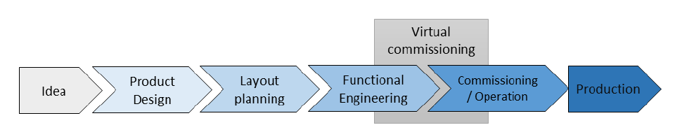
Nowadays VC has established as an important part of the engineering process of production systems. There are different phases in the mechatronical engineering process beginning with the product design, continuing with layout planning, functional engineering and ending with commissioning and production (see Figure 1) [2]. VC starts during the functional engineering and proceeds into commissioning. A virtual model of the whole production system is prepared based on data generated in these phases of the engineering process.
The virtual model reproduces the correct operation of all parts of the real production system which influence or which are influenced by the control software and hence which are essential for testing this control software. In the test setup, the tested control software (PLC program) is not simulated but runs on the real PLC hardware. From a practical point of view, a virtual model can be divided into a behavior model and a 3D geometry model [3].
A behavior model describes the logical behavior of a component and maps its reaction to an input signal on its output signal [4]. The behavior model of the whole production plant is built up based on the individual component behavior models. The component manufacturer doesn’t always provide behavior models of components (MBM – Manufacturer Behavior Model). Therefore, each company/user develops its component behavior models independently (UBM – User Behavior Model) following their particular standard.
A 3D geometry model represents the mechanics of the production plant [5] [6]. It visualizes the movement of each component depending on the control signals of the PLC program. Thereby, the component’s movement is calculated by a corresponding behavior model. Additionally, the material flow is integrated into the production system and visualized in the same model [7]. In practice, 3D geometry simulations and behavior simulations most often are executed not on one but different specialized simulation tools [4].
Furthermore, because of its complex movement the simulation of an industrial robot has to be performed separately from the simulations of the other components and then visualized in the 3D geometry model. For this purpose, the robot controller is emulated [8]. It is responsible for the execution of the native real robot program without considering changes performed during the VC. Similar to the behavior and 3D geometry simulations, an additional tool is used to simulate the robot’s movement following the commands received from the emulated or real robot program.
2.2. Enhancements on the virtual commissioning toolchain
AutomationML is a neutral data exchange format, which includes the different facets of plant engineering. It has been stepwise adopted as a standard data exchange format for engineering-related data in the AVANTI project. In Figure 2, the current toolchain of VC by EKS InTec and Daimler is presented together with different tools from project partners. The red highlighted connections were developed within the AVANTI project.
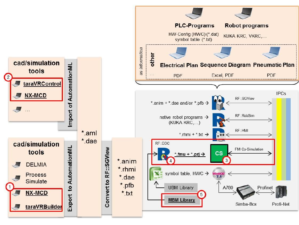
An Excel-based assistance tool is utilized to prepare a behavior model of the whole production system based on the user behavior models (UBM). On the one hand, these UBMs are created and stored as macros with WinMOD. On the other hand, the behavior model of the whole production system is executed in WinMOD. Finally, WinMOD exchanges in real time signals with the PLC and transfers calculated position signals to RF::SGView. Within the presented toolchain, the software tool RF::SGView is responsible for the visualization of the system movement during the VC. The tool RF::RobSim interprets the native robot programs and calculates the axis positions for each simulation step to realize the robot movements. RF::HMI is additionally used to visualize and modify simulation results during VC independent from the other tools. A shared memory technology (the so-called Y200) is exploited for the Interprocess Communication (IPC) between all mentioned tools.
Before the AVANTI project, the usage of AutomationML was limited to the transfer of 3D geometry models to RF::SGView. These 3D geometry models are the ones that are prepared and used for the virtual engineering of the system. In practice, only two virtual engineering tools can export simulation models in an AutomationML format, namely DELMIA V5 and Process Simulate. Although these tools can export the system’s kinematics and 3D geometry, no connection to the system’s behavior models is made.
In the frame of the AVANTI project, the toolchain of VC is enhanced by three significant changes:
- Different tools are extended by AutomationML import and/or export functionalities. An export feature is introduced into the CAD tool NX-MCD (NX Mechatronic Concept Designer) and the simulation tool taraVRBuilder to export 3D geometry and kinematic models of production systems as AutomationML files (AML and COLLADA). Additionally, the simulation tool taraVRControl, as well as NX-MCD, are extended to import 3D geometry and kinematic models from AutomationML files.
- The toolchain is extended to include improved behavior models of components. Thus the modeling of the whole manufacturing system is improved by a physically more reliable and more detailed reproduction of the component behavior. The included behavior models (i.e. UBM and MBM) are defined as Functional Mockup Units (FMU) based on the Functional Mockup Interface standard (FMI), which is a commonly used tool-independent standard for the exchange and coupling of simulation models [9]. The utilized behavior models are prepared and provided by the component manufacturer with the corresponding expertise. Finally, a real-time co-simulation tool, which interacts with the other tools by the same shared memory technology, is developed to include the FMU behavior models in the toolchain.
- The software system RF::EOC is developed to provide the co-simulation with a behavior model of the whole production system. RF::EOC constructs and configures the entire system’s behavior model based on existing component behavior models provided as FMUs by an MBM library.
The resulting data is also used for creating a virtual scene with a physics engine for a realistic visualization. With the help of co-simulation, other engineering solvers can be added to the simulation, too. As a result, a physics-based visualization excluding scripting can be produced. In physics-based animation, kinematic rigid bodies affect the motion of other rigid bodies through collisions or joints, which improves the reality of the simulation. It is also possible to model effects of sensors, actors and other production related elements. Simulation results can be visualized at real-time (runtime visualization), or a post-run visualization could be necessary because of performance issues and to provide high fidelity of the outcome.
The simulation results like the sensor signals or collision reports can be used by a test system to improve the validity of the VC. An automatic test generation tool is also another system component, which is generated in the AVANTI project.
2.3. Automated test generation for virtual commissioning
Figure 3 depicts the structure of an automated test bed as used within the AVANTI project for testing of industrial control programs.
Fig. 3 (structure of an automated test bed for the VC) is available in the original PDF.
A test engineer makes use of a test system for automated testing of a control program. The resulting report provides hints of possible malfunctions in the tested control program. The test cases have to be described formally for the purpose of automated testing. They contain descriptions of the test stimuli, the expected behavior of the control program and optional templates for human readable descriptions of test results.
With the test system developed in the AVANTI project, the test engineer can perform multiple tests executed as a batch. During a test, the test system stimulates and observes the control system, as well as the simulated mechatronic component models. Additionally, the test system can reset the control programs and simulation models. Finally, it creates a test report.
The test cases have to take into account not only the correct behavior of mechatronic components but also their malfunctions. For example, in the case of a malfunction, the control programs have to save the health of operators and machine parts, and additionally they have to signal the malfunction. Therefore, the behavior descriptions of the mechatronic components have to provide variants for normal and faulty behavior, to be addressed within different test cases.
3. Implemented Functionalities
To tackle the identified bottlenecks on the workflow in the AVANTI project new software components for data exchange were developed. Some of these software components are add-ons for existing software tools, and some of them are entirely new systems. These software components will be explained in detail in the following sections.
3.1. Y200-FMI Connector
The FMI standard for VC is applied as an extension of the current toolchain shown in Figure 2. Using the FMI standard, the modeling of component behavior models is omitted partially, because users only have to adapt prepared component behavior models (MBM) regarding their proprietary standards (UBM), if required, e.g. signal names, additional signals, particular signal dependencies, etc. Furthermore, a tool-independent simulation of behavior models via FMI as FMUs is feasible. A co-simulation environment is utilized to fulfill soft real-time requirements and to include FMU behavior models. The FMU behavior models are configured and bundled as a co-simulation setup and executed by the co-simulation software system. The Y200-FMI Connector provides an interface between WinMOD’s Y200 shared memory interface and the FMI used in co-simulation. Y200 supports different exchange data formats and allows for multiple concurrent interprocess communications. Furthermore, applications like the robot simulation (via RF::RobSim) and the HMI (via RF::HMI) also communicate with WinMOD and co-simulation via the shared memory component.
In AVANTI, linking FMUs with AutomationML was analyzed and the possibility to link signals of behavior models to kinematic axes of 3D geometry models was the particular focus (Figure 4). Currently, linking between these models is not enabled by CAD/simulation tools, which can export AutomationML data. Therefore, using an additional configuration/assistance tool of behavior models for production systems is required.
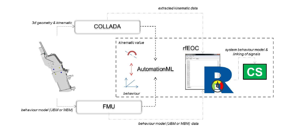
It is conceivable to extend RF::EOC with functionalities which enable the linking of behavior model with kinematics and store this information directly in AutomationML. Of course, an automated linking of both models can also be achieved, provided that an explicit identification between kinematic and behavior model is taken. For this purpose, each user has to define own standards and workflows.
3.2. NX-MCD export for AutomationML
Regarding the integrated export functionalities for the CAD tool NX-MCD, each user can export his 3D geometry model as AutomationML data and perform, if required, the VC of a production system. Thereby, two significant benefits are identified. The first one is the data exchange between CAD/simulation tools and VC tools without loss of data. In similar cases, other data formats can store only partial data, e.g. 3D geometry, colors, topology, kinematics, links to behavior models, etc. As a consequence, additional modeling has to be done for the purpose of VC, e.g. modeling of kinematics of a production system provided as STEP file. Furthermore, users are not obliged to use the VC tools which are only compatible with a particular CAD/simulation tool. For a VC tool provider, their tools are independent of other CAD/simulation tools which are used by their current or future customers. Concretely in the AVANTI project, one CAD tool (NX-MCD) and one simulation tool (taraVRBuilder) were added to the toolchain without any necessity to modify the other VC tools (RF::Suite).
3.3. tarakos export and import for AutomationML
tarakos software tools join the VC workflow at the beginning with taraVRBuilder and at the end, as a visualization tool for physics simulation results with taraVRControl. In Figure 5, the positioning of tarakos tools in the VC toolchain is presented.
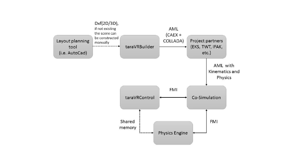
The first step in the toolchain of tarakos is the importing of 2D/3D layout and component files to create a 3D scene in taraVRBuilder. This step is not always essential because it is also possible to build a scene with standard library components of the tool. The position of the manufacturing objects and the logical structure of the material transfer like which element is connected to which one can be described in taraVRBuilder. This information together with the 3D geometry can be exported with the implemented AML export function. After exporting, the content of the data can be enriched by other tools in the work chain. The kinematics and physics of the object models can be included in the AML or COLLADA file. As the next step, the physics scene should be created with the entire information and connected with co-simulation. taraVRControl can connect directly with the physics engine as a visualization component or can connect indirectly through the co-simulation environment.
The second demonstrator is a material handling system, which is also present as hardware. This use case demonstrates the project results for physics simulation, co-simulation connection and testing system with automated test execution for PLC. The goals for the use case are:
- Realistic simulation of the virtual material handling system
- Systematic testing of the system
- Comparison of the results with the real system
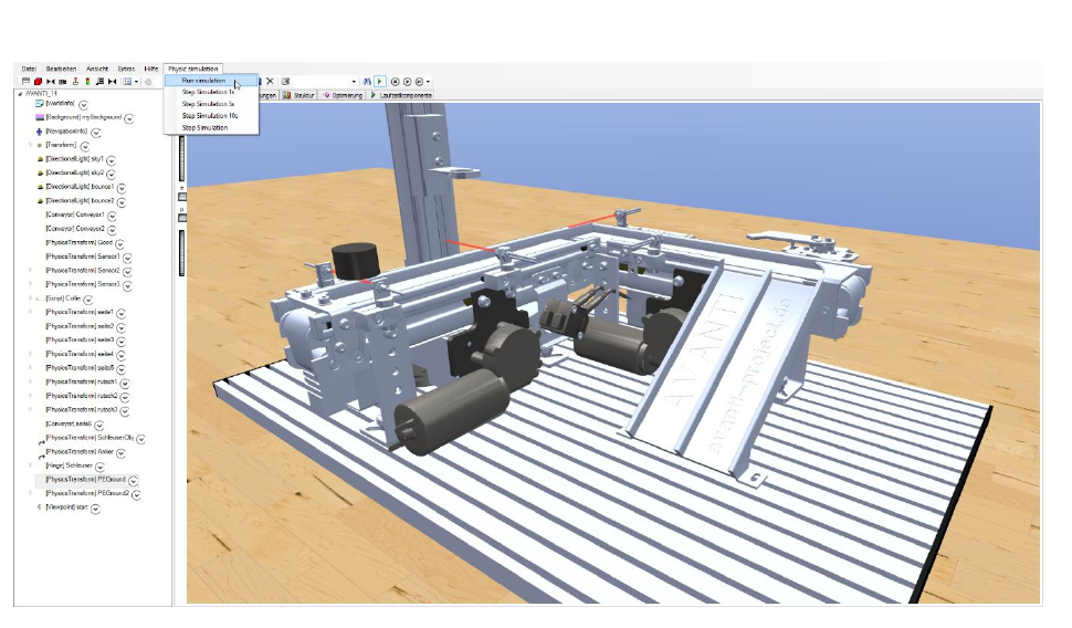
A real material handling system from the partner company Festo has been established to compare the simulation results of the virtual system with the actual behavior. The geometry of the system has been imported into taraVRControl software, which provides the visualization for the physics simulation as seen in Figure 6. The behavior of the individual logical elements is defined in FMUs. The test system for automated testing uses the sensor signals from the simulation environment and signals from the logical components to execute the tests. Software components participating in the simulation are exchanging signals with each other through the co-simulation framework.
3.4. Automated test generation tool
An automated test generation tool has been produced during the AVANTI project. The material handling demonstrator mentioned above (Figure 6) is also utilized for showing the implemented functionalities of the test tool.
Three approaches for the integration of healthy and faulty behavior of mechatronic components into FMUs for the purpose of automated testing were developed [10]:
- Polymorphic behavior description: different variants of normal and faulty behavior are embedded into the same FMU. The test system addresses the corresponding behavior variant to evaluate a particular test case.
- Dynamically changeable behavior description: the healthy behavior is provided by an inner FMU. The faulty behavior (which can be caused by events or elements of the process context) is modeled by a scripting language within a wrapper FMU including the inner FMU.
- External description of faulty behavior: the test system may trigger events within a 3D Visualization FMU, which represents the shape and physical behavior of mechatronic components as well as sensors and actors. The sensor and actor signals are exchanged with the control system by using the FMI technology. In opposite to the other approaches, disturbances triggered by the test system become visible for the test engineer by using this method.
These approaches have different degrees of reusability and flexibility and result in different effort for component manufacturers (which commonly are editors of the component behavior descriptions) and test engineers. Furthermore, these three approaches can be combined.
Fig. 7 (architecture of the test bed for the AVANTI transportation system demonstrator) is available in the original PDF.
An FMU of the demonstrator is a DLL file within a ZIP container and includes executable simulation models, which are operating system dependent, as well as an interface description. These simulation models can be generated by modern simulation tools or are compiled using portable C or C++ code. Interface descriptions (modelDescription.xml) of FMUs are based on XML [11] and include, for example, descriptions of the inputs and outputs of the FMU considered.
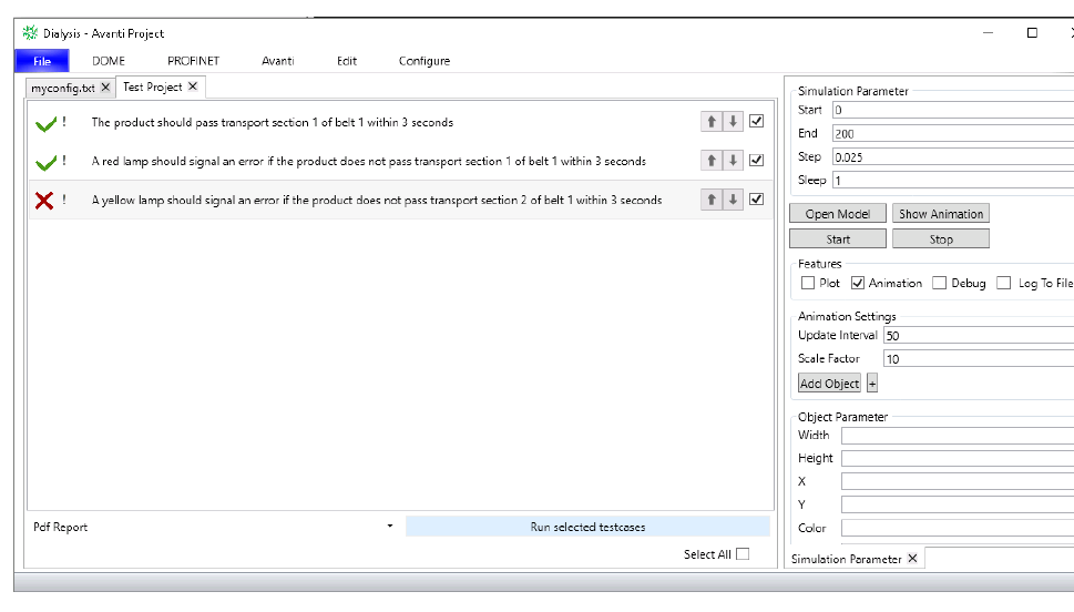
The control program is executed on a real industrial control system (PLC) and communicates via a Control System Gateway FMU with other FMUs of the test bed. A 3D simulation tool is integrated in a similar manner. Furthermore, behavior models of the component FMUs are constructed according to one of the three approaches mentioned previously. The test system is integrated into the FMI Co-Simulation Master since it requires information of nearly all FMUs. An example of a test report prepared by the test system is presented in Figure 8. Failed tests are marked with a red cross in the test report because the observations do not fit the expected behavior. They indicate a possible error in the control program.
The engineering process to prepare the VC set-up is complicated because each control system interface has to be connected with the corresponding simulation models of the mechatronic components correctly. Future engineering tools (CAD, ECAD, PLC programming IDE, etc.) will provide an engineering process based on AutomationML with pre-connected data models. For the reduction of efforts within the configuration process of simulated test environments, it must be possible to reference a behavior model of a mechatronic component within AutomationML files. Within the AVANTI project, an approach for referencing FMI based behavior models within AutomationML files was used (see Figure 9) according to results of the research project inITial [12]. That approach is described in the following.
![Figure 9: Interconnection of behavior simulations to PLC programs within AutomationML [8]](https://www.automationml.org/wp-content/uploads/2026/08/AML-2016-Strahilov-Virtual-Commissioning-Workflow-fig7.png)
AutomationML provides features to describe the structure of a production system regarding a hierarchy of mechatronic components, which are represented by individual data objects called InternalElements (IE). These IEs can be linked to each other using InternalLinks (IL).
An IL connects two information endpoints, the so-called partner sides, of the link. The information endpoints are addressed using CAEX ExternalInterfaces (EI), which are derivatives of AML standard interfaces. Information endpoints for the exchange of geometry and kinematics data are addressed using a COLLADAInterface, while endpoints for the transfer of control program parts are addressed using a PLCopenXMLInterface.
In the AVANTI project, an abstract FMUInterface has been utilized with the parent class AutomationMLInterfaceClassLib/AutomationMLBaseInterface/ExternalDataConnector. It identifies child interfaces as being related to the FMI technology.
Additionally, a generic VariableInterface was derived directly from that FMUInterface. It inherits an attribute called refURI, which denotes a Unified Resource Identifier (URI) and is of type xs:anyURI. A URI contains the following syntax elements: scheme, authority, path, query, and fragment [RFC 3986]. The fragment of a VariableInterface refURI attribute value must contain the name of a scalar variable model (ScalarVariable) of an FMU interface description (modelDescription.xml). All other syntax elements of the URI must refer to a file or an internet-based resource that addresses an FMU. Furthermore, a fragment of a URI follows directly after the delimiter “#” according to [13]. Thus, the example refURI value shown in Figure 9 refers to an FMU (st_behavior.fmu) located within a local file system. It addresses the model variable varX of that behavior model.
This approach enables control program variables to be associated with behavior model variables using AutomationML. It is the key to the efficient integration of FMI-based behavior models into automated testing of control programs. Finally, it can be used for a partial configuration of FMI co-simulation masters.
4. Communication Platform
The CoP is a web-based software system to allow shared access to model data. The essential functionality of the CoP is the data exchange of project information regardless of the location. It also provides some necessary services like version management, data security, role management, etc.
4.1. Architecture of the Communication Platform
Regarding current considerations of the AVANTI project and the knowledge about existing exchange platforms which are used in various industrial fields, e.g. in software development or in mechanical component development, the specification of the CoP was evolved for the AVANTI project and the respected partners. The developed architecture is visualized in Figure 10. It presents a simplified overview of the architecture of CoP.
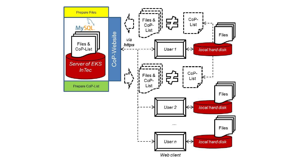
This structure is divided into two sub-architectures. The first sub-architecture focuses on the structure of the server of the CoP, namely whatever is required to save, manage and exchange files from one user to another. The server architecture also includes the user rights management relating to the use of the platform and the processed data. One of the important tasks of the architecture is to define the structure of the underlying database. This structure contains the information about user accounts, files, and modifications. MySQL database, which offers all required functionalities to store and exchange the data needed by the server, has been chosen for this purpose. MySQL also provides an Application Programming Interface (API), which can be used to connect web applications with the database [14].
The second sub-architecture involves the structure of the User Interface (UI) which is available to each user. With the UI each user can transfer files or complete models to the server and from the server. The UI will be dependent on the dedicated user rights that are stored in the database. They influence the appearance of the UI and limit or unblock functionality of each user suitable to its rights.
To implement the data exchange between both subsystems, they communicate with each other via the standard Internet communication protocols. So, one important requirement concerning the data security to the CoP was to use secure data transfer between both involved systems (i.e. server and database). Regarding this condition, the chosen communication protocol must provide data encryption, e.g. HTTPS, or if the data is transferred through an unencrypted protocol like HTTP, the data must be encrypted before it will be transferred between client and server and it has to be decrypted on the destination end of the connection. This transfer can be for instance achieved by using a VPN (Virtual Private Network) connection between client and server which is encrypted, and then data transferred inside this tunnel connection can be transferred in an unencrypted format.
Data encryption should be conducted automatically by the software without explicit handling from the user. For the prototypical implementation of the CoP the communication protocol HTTPS was used, because an implementation of an encryption application is complex and would be above development time and budget in AVANTI for the CoP. Encryption is a standard technology, and the usage of already existing implementations is preferred instead of a reinvention. Despite that, a further step could be to integrate an encryption system to increase the security of the file transfers between users and server.
Another important point of the communication is the additional transmitted CoP-List which contains information about the files that a user will send to or receive from the server. Based on the information included in this file, the CoP deduces the state of the files. Thereby, the CoP application determines if a file is modified or not as well as whether that file version is older than the current file version on the server or not. Regarding the various states of the files, the application decides how to process each file and gives feedback to the user via the web interface. In specific cases, the user should take the decision about what the CoP has to do with the file.
The web interface is also part of the CoP architecture because it is the tool the user interacts with and where file exchanges with the server are realized. Based on the defined requirements of the CoP, the web interface must be easy and intuitive to operate. Another requirement to the UI respectively the web interface is that it could be used with common web browsers that support the latest HTML5 standard [15]. The advantage of the choice of the web-based solution instead of standalone client architecture is that for the users of the CoP no additional software needs to be installed, and the solution is independent of the client’s operating system. Another advantage of the web-based solution is that no maintenance to additional software and no additional updates must be done on the client’s side. Current development of the web standards allows generating simple, responsive, and easy to use user interfaces with a moderate amount of development work mostly due to no need for operating system or client-side system configuration to be concerned.
From this point of view, the development in AVANTI was focused mainly on the internet browsers following the current web HTML5 standard, because of their widespread use in the industry and academia. The server side processing will generate web code compatible with the current client browsers, limiting client side requirements. JavaScript and AJAX (see [16] for more information) on the client side will, in turn, allow for creating rich user experience with asynchronous communication to the server, alleviating the need for full page refreshing to update the client’s view.
4.2. Implementation of the Communication Platform
As previously said, a web-based user interface enables an easy usage of the CoP across different locations (see Figure 11). A user login is required for CoP similar to most websites. For this purpose, CoP’s administrator has to create an account for each user and define a username and a password. During first login, each user is requested to change his password provided by the administrator.
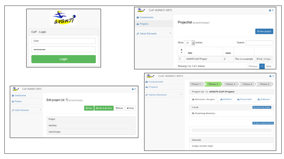
After the successful login, the user gains rights to all projects which are associated with his account. For example, if the user is the project manager, he has the right to edit the project. If required, a project manager can change all attributes of a project, e.g. name, description, roles, add or remove users from the projects, and change rights of users.
The project editing section is divided into the three fields “Project”, “Sections”, and “User/Group”. In the field “Project”, project based information is stored, e.g. title, description, etc. Field “Sections” contains all defined sections for the project. These sections represent an additional project division, e.g. mechanic, electric, pneumatic, PLC software, etc. On the one side, this section serves to create an overview of the several project contents and, on the other side, provides the distribution of access rights to users. A fixed section structure is not provided by CoP directly and has to be defined by the project manager. As next field, “User/Groups” enables distribution of user access rights to the sections and editing/removing of users to the project. During the adding of a user to the project, the current user receives rights for a minimum of one group and with this, rights to one section. As an example, a user with the permission for the group “mechanic construction” receives automatically rights to the section “mechanic design”.
Under the section “Rolelist”, all roles and groups defined in CoP can be edited, added or removed. A clear distinction between roles/groups which are provided by CoP, and roles/groups which are defined project specific, was made in AVANTI. Thereby, CoP also enables to derive project specific roles/groups from already existing CoP roles/groups. Additionally to the project management, the new user as well as groups can be added to a CoP project independently via the functions provided in section “Admin Elements → User/Groups”.
In each section, users can add files to the section. For this purpose, the user has to choose a local folder which contains the target files. As the following step, a list of all files contained in the current folder is provided via the user interface. In this list, additional information is also given about the status of each file, e.g. new file, removed file, changed file, etc. Furthermore, each/all files in a section can be downloaded.
4.3. Integration of the Communication Platform into the toolchain
The CoP could be used to exchange several files between the tools in the toolchain. As an example, a 3D geometry model is changed via a CAD/simulation tool. The modified model has to be exported via an AML exporter and provided as AutomationML files for the purpose of VC via CoP. At the same time, a robot program was also changed by the robot programmer and uploaded to CoP. Consequently, the user who is responsible for the preparation of models for VC receives information about both updates, and can regard these changes. As a further option, CoP can be extended by functionalities to read and interpret AutomationML files directly and identify changes based on file contents.
5. Business Opportunities with the Improved Toolchain
AML provides a standardized data format for the exchange of behavior models between various applications. Enabled by AML, the component manufacturer has a standardized, easy to use, and reliable distribution channel for his component behavior models. The component manufacturer has the opportunity to provide and sell behavior models together with support as an additional service.
With an AML improved toolchain, the OEM can utilize behavior models more accurately, easier and faster. With those, the OEM can specify its requirements more precisely and with more details. Based on a more precise requirement specification the OEM can request from the production line manufacturer a better fulfillment of his requirements. Additionally, the OEM’s ability increases to evaluate if its demands are fulfilled (after the delivery of the product but also partly during the product’s production process).
Reusable physical component models and existing data exchange interfaces reduce the engineering effort to build up simulation models. If physical component models are provided and a physics engine is available, the need to prepare a separate animation of the components is eliminated. This reduces the development effort when introducing new component models into the software tool.
Based on improved VC models and more precise requirement specifications the tester can guarantee and sell higher test safeguarding and test coverage. With more reliable models of the plant and the requirements, an automatic test execution becomes possible allowing for better test coverage in less time and with less manual adaptations.
It is still a common practice in the industry to exchange data by email and often changes are not communicated with the person who prepares the simulation models for the VC. As a consequence, simulation models used for the evaluation of PLC programs are not up to date, and the evaluation becomes insufficient. In most cases, such data changes and outdated models are identified only when the real system is already constructed. Consequently, the PLC programs are modified and corrected under high time pressure. To prevent those problems, the CoP provides an environment to exchange data during the development process of production systems. The primary role of CoP is to provide various project partners with different backgrounds, e.g. mechanical engineers, electrical engineers, software engineers, etc., with a tool for a reliable data exchange. Thereby, changes or updates are communicated to all project partners and logged into a management system.
Regarding CoP, two different business opportunities can be identified. First, CoP can be developed and provided to the users as an independent tool. In this case, one company is responsible for developing CoP and supporting its customers. Second, a company develops CoP and is in charge of its support and update. In both cases, CoP’s users can use CoP to exchange data internally as well as externally with project partners.
6. Summary
In this paper, improvements of the communication in the VC toolchain are presented, which were developed in the AVANTI project. Four main enhancements are introduced: 1) different tools like NX-MCD and the tarakos software kit are extended by AutomationML import and/or export functionalities, 2) behavior models of components are defined as FMU models and combined in a co-simulation, 3) a tool for automated test generation for PLCs is developed, which utilizes behavior models and test descriptions, and 4) a communication platform is created for the data exchange between project partners.
The AutomationML format is a core part of these efforts as it includes different information aspects of the production planning. It is a standardized, easy to use, and reliable distribution channel for virtual models. As the maturity of VC models is improved and requirement specifications are defined more precisely, it becomes possible to guarantee and sell higher test safeguarding and test coverage. Based on that, an automatic test execution becomes possible, that allows for better test coverage in less time and with less manual adaptations. With the help of the CoP various project partners of different backgrounds have a solution for reliable data exchange.
References
[1] M. Bergert, S. Höme and L. Hundt, “Verhaltensmodellierung für die Virtuelle Inbetriebnahme,” in VDI Wissensforum GmbH (Hg.): Tagungsband Automation, 2010.
[2] A. Lüder, L. Hundt and S. Biffl, “On the suitability of modeling approaches for engineering distributed control systems,” in 7th IEEE International Conference on Industrial Informatics, 2009.
[3] F. Damrath, A. Strahilov, T. Bär and M. Vielhaber, “Establishing Energy Efficiency as Criterion for Virtual Commissioning of Automated Assembly Systems,” in Procedia CIRP 23, 2014.
[4] S. Süß, A. Strahilov and C. Diedrich, “Behaviour Simulation for Virtual Commissioning using Co-Simulation,” in 20th IEEE International Conference on Emerging Technologies and Factory Automation, Luxembourg, 2015.
[5] A. Strahilov, M. Mrkonjić und J. Kiefer, Development of 3D CAD simulation models for virtual commissioning, Karlsruhe: Proceedings of TMCE 2012, 2012.
[6] J. Kiefer, M. Bergert und L. Ollinger, „Virtuelle Inbetriebnahme – Standardisierte Verhaltensmodellierung mechatronischer Betriebsmittel im automobilen Karosserierohbau,“ ATP-Edition, pp. 40–46, Juli 2009.
[7] F.-F. Lacour, Modellbildung für die physikbasierte Virtuelle Inbetriebnahme materialflussintensiver Produktionsanlagen, München: Herbert Utz Verlag GmbH, 2011.
[8] S. Süß, S. Magnus, M. Thron, H. Zipper, U. Odefey, V. Fäßler, A. Strahilov, A. Klodowski, T. Bär and C. Diedrich, “Test methodology for virtual commissioning based on behaviour simulation of production systems,” in 21st IEEE International Conference on Emerging Technologies and Factory Automation, Berlin, Germany, 2016.
[9] MODELISAR Consortium, “Functional Mock-up Interface for Co-Simulation,” 2010.
[10] M. Thron, H. Zipper, S. Magnus, S. Süß, C. Göbeler, Z. Liu und C. Diedrich, „Beschreibung des normalen und gestörten Verhaltens mechatronischer Komponenten für den automatisierten virtuellen Anlagentest,“ in AUTOMATION 2016, 07.–08.06.2016, VDI Wissensforum GmbH, Baden-Baden, 2016.
[11] F. Yergeau, T. Bray, J. Paoli, C. M. Sperberg-McQueen und E. Maler, „Extensible Markup Language (XML) 1.0. W3C Recommendation,“ 2008.
[12] O. Niggemann, N. Moriz, S. Faltinski, O. Graeser, M. Barth und A. Fay, „Integration und Anwendung von objektorientierten Simulationsmodellen in AutomationML,“ in VDI Wissensforum GmbH (Hg.): Tagungsband Automation, 2011.
[13] L. Masinter, T. Berners-Lee und R. T. Fielding, „RFC 3986 Uniform Resource Identifier (URI): Generic Syntax,“ 2005.
[14] Oracle Corporation, “MySQL Editions,” 2016.
[15] W3C HTML Working Group, “HTML5. A vocabulary and associated APIs for HTML and XHTML,” 28 October 2014.
[16] W3Schools, “AJAX Tutorial,” Refsnes Data.
BibTeX
@inproceedings{strahilov2016vc,
  author    = {Strahilov, Anton and Yemenicioglu, Ender and Thron, Mario and Zipper, Holger and Riedl, Matthias and Zimmermann, Ulf and Wior, Ireneus and S{\"u}{\ss}, Sebastian},
  title     = {Improving the transition and modularity of the virtual commissioning workflow with {AutomationML}},
  booktitle = {Proceedings of the 4th AutomationML User Conference},
  address   = {Esslingen, Germany},
  month     = oct,
  year      = {2016},
  publisher = {AutomationML e.V.},
  url       = {https://www.automationml.org/conferences/conference-highlights/improving-the-transition-and-modularity-of-the-virtual-commissioning-workflow-with-automationml/}
}
How to Cite
A. Strahilov, E. Yemenicioglu, M. Thron, H. Zipper, M. Riedl, U. Zimmermann, I. Wior, S. Süß: “Improving the transition and modularity of the virtual commissioning workflow with AutomationML”, Proceedings of the 4th AutomationML User Conference, Esslingen, Germany, 18–19 October 2016.
This page is a text rendering of the original conference paper, published for accessibility and search. The PDF is the authoritative version. Figures 3 and 7 are available in the PDF. If you are an author and would like a correction, please contact office@automationml.org.