
Prerna Bihani (Software Technologies and Applications, ABB Corporate Research Center Germany, Ladenburg) · Rainer Drath (Faculty of Technology, Pforzheim University of Applied Sciences)
Presented at
5th AutomationML User Conference
24–25 October 2018, Mölndal/Gothenburg, Sweden
Hosted by ABB
Type
Full paper, 6 pages
Open access
Republished by the AutomationML association. Copyright remains with the authors.
Abstract
Automating data exchange in a heterogeneous engineering tool environment is considered a challenge due to typically large amounts of differences between data models of the involved tools. [6] defines a levels of conceptual interoperability model, and this paper interprets it for the application of AutomationML in a heterogeneous engineering tool landscape. The focus of the present paper is on level 3 or semantic interoperability which requires that a mapping between the different engineering tool data models be performed. Performing this mapping is a major effort and, as a result, most engineering data exchange is still executed through manual means via paper format since a human is needed to at least interpret the particular semantics of the data. In this paper, three basic approaches for enabling semantic interoperability are examined and the benefits and drawbacks of each method are explored. Following the analysis, a best practice proposal is described. Possible future extensions of this approach are also described.
Keywords: automated data exchange; interoperability; engineering data models; heterogeneous tools; semantic standardization; AutomationML; CAEX
I. Introduction
Engineering is characterized by tool chains: across different phases of engineering, multiple tools of different vendors are used in order to perform different engineering tasks, e.g. 3D product planning, factory layout planning, software engineering, hardware engineering etc. [1][2]. In the last decades, the key focus of engineering tool vendors was on optimizing the functionality of the tools themselves. Meanwhile, the growing maturity of engineering tools makes it difficult to differentiate comparable tools by their tool functionality. Furthermore, growing complexity of automation systems, increasing number of engineering artifacts, and growing heterogeneity of automation systems under rising cost and time pressure require innovations in managing the consistency and correct usage of engineering data across all tools in the tool chain. Hence, interoperability of engineering tools raises into focus, which is seen as a key future differentiator and especially difficult to achieve when engineering tools originate from different vendors [3].
A common definition of interoperability is “the ability of two or more systems or components to exchange information and to use the information that has been exchanged” [4]. Since engineering tools are usually model-based systems, engineering tool interoperability requires interoperability between their models. Typically these models are abstractions of real world objects and phenomena purposefully designed to address problems of the respective domains. Consequently, differences between the models can arise at many different levels ranging from syntax usage to semantical terms to operational procedures to underlying assumptions and constraints.
Interoperability as defined above comprising of information exchange and usage can accordingly be understood using the Levels of Conceptual Interoperability Model (see Fig. 1). The model with its increasing levels of interoperability was first described in [5] and later extended in [6]. A presentation of the underlying mathematical framework using model theory can be found in [8] and [9]. Initially developed for M&S engineering for military simulation software, the interoperability model has since been referred in diverse applications [10][11][12][13].
Fig. 1 (Levels of Conceptual Interoperability Model [7]) is available in the original PDF.
It can be interpreted in the following manner for engineering tools and their data models:
- Level 0 — No Interoperability: No exchange of information between the engineering tools is possible or intended. Here, engineering tools are typically standalone, closed systems with no electronic interfacing possibilities, e.g. control engineering tools of competitors that are not designed to exchange their data.
- Level 1 — Technical Interoperability: A communication protocol exists for exchanging raw data between engineering tools together with requisite exporter and importer interfaces. A first step in interoperability, the engineering tools at this level are capable of exchanging bits and bytes or signals.
- Level 2 — Syntactic Interoperability: The structure or format of the data can be unambiguously interpreted between the engineering tools, e.g. via use of a common data format such as Excel, XML or AutomationML. As a result, tools can clearly interpret symbols and perform related functionalities, e.g. difference calculation, using their exporter/importer interfaces.
- Level 3 — Semantic Interoperability: The semantic or informational content of data can be aligned between the engineering tools via use of a common information exchange reference model or a neutral semantic standard. This means that the meaning of the data is shared, consequently the tools with the help of their interfaces can clearly interpret terms.
- Level 4 — Pragmatic Interoperability: The context in which data is used, associated methods and procedures within the different engineering tools are made known, allowing common understanding about the use of terms within different engineering tools. At this level of interoperability, tool interfaces could be used to access or extend other methods.
- Level 5 — Dynamic Interoperability: Any changes in the models’ constraints or assumptions can be communicated for alignment about the effects on operations between the engineering tools. As a result, there is common understanding about appropriate interpretation of the information exchanged between engineering tools.
- Level 6 — Conceptual Interoperability: The conceptual models of the engineering tool models, i.e. used assumptions and constraints, are documented and aligned as part of a common reference model for the engineering tools, ensuring the same underlying theory. Full understanding between the tools is reached at this highest level of interoperability.
With integratability or Levels 1 and 2 already addressed via the openness criteria [14] and interpretation of data formats [15][16][17][18][19] respectively, the focus currently lies on Levels 3 and above. The central aspects of interoperability are covered by Levels 3 and 4, whereas Levels 5 and 6 address composability at higher modelling levels. The exchange of semantics or informational content and pragmatics or utility content are the focus of our current paper (Level 3) and continued research (Level 4).
The AutomationML data format [17][18] itself is explicitly designed for Level 2 and provides only basic role libraries for Level 3. The strict separation of syntactic neutrality and semantic expressiveness is intended: the mechanisms of data modelling allow for modelling of any semantics in user-defined or standard libraries. In contrast to other data formats which directly aim for Level 3, AutomationML is extensible and flexible for future integration of further semantic standards.
The question is how to beneficially make use of this flexibility to perform data exchange in a heterogeneous engineering tool landscape without relying upon neutrally-defined semantics or a common data model in participating tools. We aim for a best practice recommendation and demonstrate how to reach semantic interoperability in a cost efficient and elegant way, useful for practical applications. In particular, in this paper we describe three basic approaches for AutomationML-based semantic mapping together with the benefits and drawbacks of each approach. Section II describes general approaches to perform semantic mappings and analyzes their benefits and drawbacks. Section III recommends a preferred method and explores it in detail. The proposed method has been implemented in an industrial data exchange at ABB HVDC and conceptually published in [20]. Areas of further extension to overcome current limitations of the preferred method and achieve pragmatic interoperability are presented in Section IV. The paper concludes with closing remarks in Section V.
II. General Approaches to Perform Mappings Between Data Models
A. Overview
Consider a tool chain from Tool A to Tool B meeting syntactic interoperability (Level 2) as described in Section I. The data flows from the database of Tool A through an exporter into a file (with a common or interpretable data format), and then through an importer into Tool B (see Fig. 2).
Fig. 2 (three general layers to place mapping functionality) is available in the original PDF.
For achieving interoperability at the semantic level (Level 3), a mapping would need to be performed between the engineering tools. The mapping definition and execution may generally be placed on three different layers, see Fig. 2:
- Layer A: in the tool layer
- Layer B: in the exporter and importer interface layer
- Layer C: in the intermediate file data model layer
From the industrial perspective, these basic approaches have to furthermore be evaluated for their complexity, cost and effort in terms of initial development, maintenance, regulation, risk and ownership.
B. Option 1: harmonizing on tool layer (Layer A)
A most obvious and ideal method to solve the mapping problem between different data models across different tools is to harmonize the semantics used in the data models across all participating engineering tools. This method is typically applied in tool suites using common databases where the semantic harmonization happens in a vendor specific and proprietary way. The key benefit is the elegant avoidance of any mapping, with common semantics automatically leading to semantic interoperability across all participating tools.
However, this method suffers from a semantic standardization deadlock, as described in [22], implying stalling of progress. This method, due to practical reasons, is usually bound to the ownership of all participating tools, which has the power to set the semantic standard. The acceptance on the market is limited since it requires that customers bind themselves to one common vendor, a significant risk. Furthermore, a common database requires high effort in continuously agreeing on the semantics in case of change requests and reduces the general willingness and ability of the individual tool participants to innovate. As a result, the innovation speed of those tools is significantly reduced compared to independent tools. Applied in a vendor independent way, this method requires a powerful standardization community that develops neutral engineering semantics. However, this has not yet been achieved and would constitute a long term activity. According to [22] and [23], for most cases, this approach is not suitable for practical industrial purposes. Industrial users usually prefer to select their best-in-class tools individually.
C. Option 2: Mapping between data models in exporters and importers (Layer B)
A second and very popular option is to keep the tools A and B independent and instead perform the semantic mapping in Layer B, i.e. the importer and exporter layer. The mapping functionality would in this case be built into the exporter and importer. There are three suboptions: 1) the exporter needs relevant knowledge of the Tool B data model; 2) the importer requires relevant knowledge of the Tool A data model; or 3) the exporter and importer interact via an intermediate neutral data model for the relevant aspects.
In any of the above cases, innovations in either tool would require corresponding modifications of the exporter and/or importer, leading to a combinatorial version explosion of these software interfaces. Furthermore, case 3) would additionally require continuous adaptation of the neutral data model with related innovations in Tools A or B. Since there is a variety of engineering tools in the market that publish new versions every year, the maintenance effort scales significantly with more than two participating tools.
Although this option overcomes the tremendous initial development effort required for harmonizing in Layer A, significant maintenance effort would nevertheless be required in Layer B, followed by the need of version support for all combinations of upcoming versions of Tools A and B over time. Moreover, some oversight of the tools development may be needed to ensure that changes in the data models can be appropriately conveyed for representation in the exporter-importer interfaces. Consequently, ownership of some degree may also be required.
D. Option 3: Mapping between data models in the intermediate data file (Layer C)
The third option is to keep the tools A and B as they are, and to make the exporter and importer software generic without semantic knowledge about other data models, and to instead model all the required semantic mappings directly into the data model of the intermediate data file in Layer C. The effect of this approach is that all mappings contain interoperability information between the data models that are readily interpretable by the exporter and importer software. Consequently, modifications of the data model in Tool A or B only require adaptations of the mapping in the intermediate file layer; no software modification in the other tools or in the exporter and importer layer are necessary.
Using this option, both the initial development and maintenance effort of the exporter and importer interfaces are low. The tools innovate independently and no regulation is required. All risk is reduced to successfully maintaining the intermediate model. Furthermore, this approach has proven successful for Level 3 interoperability and allows for several efficiency benefits as observed in an actual industrial scenario [20][21]. We therefore recommend it as a best practice for exchanging engineering data. The following section explains the method in details, followed by possible extensions in Section IV.
III. Semantic Mapping in the Intermediate Data Model
A. Description of the method
The main idea is to map the semantically equivalent parts of the source and target engineering tools in the data model of an external intermediate file format using source tool semantics. The chosen intermediate file format is AutomationML [17][18][26][27] since it allows for exchange of proprietary semantics in a syntactically neutral format and follows common object-oriented design principles. The method can be described as follows:
- Experts on participating tools manually determine the data objects relevant for data exchange based on source tool semantics. For each such data object:
- A System Unit Class is created based on source tool semantics.
- A SourceToolID attribute is assigned to the System Unit Class for storing the data object’s ID in the source tool.
- An additional Content attribute is assigned for storing the data object’s description and unit in the corresponding Content.Description and Content.Unit attribute value fields.
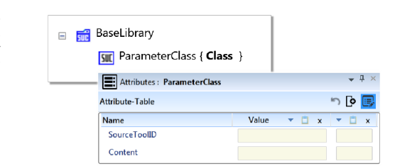
Fig. 3 below illustrates this by means of a System Unit Class named ParameterClass.
- A System Unit Class Library is created for each source tool as a type library containing System Unit Classes for the relevant source tool data objects as defined in step 1. Furthermore, to each System Unit Class, a target tool ID storage attribute is added for each tool requiring data import of the corresponding data object (as determined by experts in Step 1).
- During data exchange, each exporter tool reads the System Unit Class Library for its source tool. For each SystemUnitClass within the library it creates an instance of it in the InstanceHierarchy. It reads the provided source tool ID, finds the corresponding value of the data object in the source tool, and finally writes this value in the Content.Value entry, keeping the semantics of the source tool. Note that the exporter itself does not know of any target tool, rather it only instantiates the predefined SystemUnitClass containing mapping attributes for any target tools.
- The resulting AutomationML file with exported values is passed on to each of the target tool importers for importing relevant parameter values into the target systems. Each importer filters the relevant Internal Elements of the Instance Hierarchy using the corresponding target tool ID attribute (objects without the mapping identifier attributes are safely ignored). For each such Internal Element, it imports the Content.Value into the appropriate field in the corresponding target tool given by the target tool ID attribute value.
In the described method, the exporter software does not require any knowledge about a neutral data model or target tool data models. Similarly, the importer requires no knowledge about source tool semantics or any semantics in the neutral format as it only looks for relevant mapping information in a mechanical and transparent way. As a consequence, both the exporter and importer remain generic. In case of changes in the source or target tool data models, only the intermediate data model with mapping information requires update.
B. Simple example illustrating the method
The above method is illustrated below using a small example involving a source tool A and a target tool B (Fig. 4).
Fig. 4 (example of mapping in Layer C) is available in the original PDF.
- The experts on Tools A and B determine that a source tool output parameter with ID N corresponds semantically (e.g. for volume of a particular tank) to Tool B input parameter with ID Num, and thereby declare its value to be of interest for data exchange from Tool A to Tool B. A neutral System Unit Class Library is created with a “ParameterClass”, see “BaseLibrary” in Fig. 3. Additionally, SourceToolID and Content attributes are assigned to this class for storing the parameter ID and content information (e.g. description, unit, sub-attributes) of individual tool parameters.
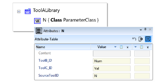
- Next, from the neutral “ParameterClass”, a source tool specific System Unit Class named “N” is created and stored in the source tool specific System Unit Class Library, see “ToolALibrary” in Fig. 5. The “SourceToolID” attribute is assigned value N, a new attribute “ToolB_ID” is created for tool B with value Num and a further attribute “ToolC_ID” is introduced for a third target tool C with value Val.
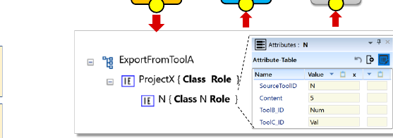
- During data exchange, Tool A exporter reads the neutral class library file and instantiates each System Unit Class in “ToolALibrary” within the Instance Hierarchy, see “ExportFromToolA” in Fig. 6. It accesses the source tool value of parameter N using its property SourceToolID.Value, reads the value “5” within the source tool and writes this value into the Content.Value field.
- Finally, Tool B importer reads the intermediate AutomationML file prepared by the exporter. It looks for all instances with a ToolB_ID attribute, i.e. all Internal Elements that are relevant for import into Tool B. For parameter N, it finds a Tool B identifier attribute and hence a parameter of interest. It inserts the parameter value provided by Content.Value into the Tool B field having ID that matches ToolB_ID.Value. Importing for Tool C works similarly. Data exchange is now complete.
Note that the described procedure allows developing importer and exporter software generically and having no knowledge about the “other” data format. This remains unchanged whenever a new tool is added into the data exchange chain, or in case of change in parameter IDs, or even with the introduction of new parameters or modification of existing ones. We achieve Level 3 (semantic interoperability) without having a common data model in the tools or tool interfaces with additional knowledge about third party data models. The mapping is determined by common agreement between the experts and is baked into the intermediate data model. Any changes in the data model are automatically reflected in the exporter and importer operations.
IV. Possible Extensions of the Proposed Method
The proposed approach has certain limitations described below which we currently aim to overcome within the framework of the research and development project INTEGRATE.
The preferred method currently requires experts to determine the semantically equivalent objects as well as explicit mapping in the data model in advance of operation. However, in industrial scenarios with multiple tools and increasingly large amounts of data to be exchanged, it may be infeasible to have all relevant experts identify the required mappings in advance. Instead, identification of mappings relevant for particular scenarios and based on sender-receiver interaction during operations may be a more viable approach for initialization of data exchange and gradual extension of exchanged items. We currently research ways to enable such dynamic mappings in a user-friendly manner.
Another constraint of the current approach is that it allows for 1:1 semantic mappings where the source tool data objects exactly correspond in meaning to target tool data objects and no transformation is required for usage in the target tool, i.e. any required processing must be performed either prior to or after the data exchange within the respective tools. A need for general m:n mappings for hierarchical object models was noted in [24] and the expressibility of corresponding relations in AutomationML is presented in [28]. As an extension of the proposed method we currently investigate inclusion of such transformations together with an intermediate processing layer, in keeping with the general principle of unaltered tools and tool interfaces.
Thirdly, we look at ways to render methods and procedures available between tools using AutomationML towards enabling pragmatic interoperability or Level 4 of the Levels of Conceptual Interoperability Model (Fig. 1).
In the future, the collected mappings information could serve as a common reference model and basis for formation of a common data model by standardization communities.
V. Conclusion
This paper explains a core technical aspect of [20] which describes a concept to achieve data exchange across multiple engineering tools via AutomationML without the need of harmonization of data models upfront. The ideas have been successfully introduced for usage in an industrial scenario. The focus of the present paper is a comparison of mapping methods using A) tool layer, B) interface layer or C) data model layer.
In contrast to the common practice of positioning mapping information in Layers A or B, the authors propose to use Layer C for efficiency reasons. Since semantic standardization and harmonisation across multiple tools is a significant effort that usually runs into a standardization deadlock, the recommended method and its possible extensions provide a powerful means of overcoming the need and efforts for harmonization in the engineering tools or even the exporter and importer interface level development and maintenance. It offers a low-cost and minimum effort solution to the problem of data exchange in a heterogeneous tool landscape with varying semantics.
By externalizing the semantical instructions from the tools into the neutral data model on Layer C using an AutomationML-based neutral class library, it is possible to retain the original data models of the tools and program exporter and importer interfaces generically, thereby allowing for immediate data exchange. Finally, the data exchange can be developed with immediate success without waiting on standards, because it decouples the industrial project pressure and long term standardization activities, and allows for stepwise standardization over time as proposed in [22].
References
[1] A. Fay, “Efficient engineering of complex automation systems,” Will traffic automatically be safer? Braunschweig, 2009, pp. 43–60 (in German language).
[2] S. Biffl, W. Sunindyo, T. Moser, “Bridging Semantic Gaps Between Stakeholders in the Production Automation Domain with Ontology Areas,” Proceedings of the 21st International Conference on Software Engineering & Knowledge Engineering (SEKE 2009), Boston, USA, 2009, pp. 233–239.
[3] R. Drath and M. Barth, “Concept for interoperability between independent engineering tools of heterogeneous disciplines,” ETFA 2011, Toulouse, 2011, pp. 1–8.
[4] IEEE Standard Computer Dictionary: A Compilation of IEEE Standard Computer Glossaries, New York, NY, 1990.
[5] A. Tolk, J. A. Muguira, “The Levels of Conceptual Interoperability Model”. IEEE 2003 Fall Simulation Interoperability Workshop, IEEE CS Press (2003).
[6] C. Turnitsa, “Extending the Levels of Conceptual Interoperability Model,” IEEE 2005 Summer Computer Simulation Conference, IEEE CS Press (2005).
[7] C. Turnitsa and A. Tolk, “Knowledge representation and the dimensions of a multi-model relationship,” 2008 Winter Simulation Conference, Miami, FL, USA, 2008, pp. 1148–1156.
[8] A. Tolk, “Interoperability, Composability, and Their Implications for Distributed Simulation: Towards Mathematical Foundations of Simulation Interoperability,” 2013 IEEE/ACM 17th International Symposium on Distributed Simulation and Real Time Applications, Delft, 2013, pp. 3–9.
[9] A. Tolk, S. Y. Diallo and J. J. Padilla, “Semiotics, entropy, and interoperability of simulation systems — Mathematical foundations of M&S standardization,” Proceedings of the 2012 Winter Simulation Conference (WSC), Berlin, 2012, pp. 1–12.
[10] E. Wassermann and A. Fay, “Interoperability rules for heterogenous multi-agent systems: Levels of conceptual interoperability model applied for multi-agent systems,” 2017 IEEE 15th International Conference on Industrial Informatics (INDIN), Emden, 2017, pp. 89–95.
[11] A. Tolk, “Architecture constraints for Interoperability and composability in a smart grid,” IEEE PES General Meeting, Providence, RI, 2010, pp. 1–5.
[12] N. Kolbe, S. Kubler, J. Robert, Y. Traon, “PROFICIENT: Productivity Tool for Semantic Interoperability in an Open IoT Ecosystem,” Proceedings of the 14th EAI International Conference on Mobile and Ubiquitous Systems, November 7–10, 2017, Melbourne, Australia.
[13] M. Robkin, S. Weininger, B. Preciado and J. Goldman, “Levels of conceptual interoperability model for healthcare framework for safe medical device interoperability,” 2015 IEEE Symposium on Product Compliance Engineering (ISPCE), Chicago, IL, 2015, pp. 1–8.
[14] M. Barth, R. Drath, A. Fay, F. Zimmer and K. Eckert, “Evaluation of the openness of automation tools for interoperability in engineering tool chains,” Proceedings of 2012 IEEE 17th International Conference on Emerging Technologies & Factory Automation (ETFA 2012), Krakow, 2012, pp. 1–8.
[15] ISO 15926: Industrial automation systems and integration – Integration of life-cycle data for process plants including oil and gas production facilities (2007).
[16] DEXPI: Data exchange with ISO 15926 – A way to improve doing business (2012).
[17] IEC 62714: Engineering data exchange format for use in industrial automation systems engineering (AutomationML) (2012).
[18] R. Drath, Data exchange in plant design with AutomationML. Integration with CAEX, PLCopen XML and COLLADA. Springer (VDI-Buch), Heidelberg (2010).
[19] PLCopen, http://www.plcopen.org/ – accessed 03.03.2015.
[20] P. Bihani and R. Drath, “Concept for AutomationML-based interoperability between multiple independent engineering tools without semantic harmonization: Experiences with AutomationML,” 2017 22nd IEEE International Conference on Emerging Technologies and Factory Automation (ETFA), Limassol, 2017.
[21] P. Bihani, R. Drath, “Collaboration Manager automates engineering data exchange,” ABB Review, 3/2017, pp. 30–35.
[22] R. Drath and M. Barth, “Concept for managing multiple semantics with AutomationML — Maturity level concept of semantic standardization,” Proceedings of 2012 IEEE 17th International Conference on Emerging Technologies & Factory Automation (ETFA 2012), Krakow, 2012, pp. 1–8.
[23] T. Tauchnitz, „Schnittstellen für das integrierte Engineering“. atp – Automatisierungstechnische Praxis 56 (2014) H. 1-2, S. 30–34.
[24] R. Drath, „Bäumchen wechsle Dich – Tücken beim automatischen Abgleich hierarchischer Objektstrukturen“. Softwaretechnik – Trends, Band 26, Heft 4, S. 14–19, ISSN 0720-8928, GI Fachausschuss Softwaretechnik und Programmiersprachen, Siegen, 2006.
[25] R. Drath, “Let’s talk AutomationML – What is the effort of AutomationML programming?” Proceedings of the IEEE Conference on Emerging Technologies and Factory Automation (ETFA), September 2012.
[26] IEC 62714: Engineering data exchange format for use in industrial automation systems engineering (AutomationML). September 2012.
[27] www.automationml.org
[28] A. Lüder, J. Pauly, M. Wimmer, “Modelling consistency rules within production system engineering,” Proceedings of the 14th IEEE International Conference on Automation Science and Engineering (CASE), Munich, Germany, August 20–24, 2018.
BibTeX
@inproceedings{bihani2018semantic,
  author    = {Bihani, Prerna and Drath, Rainer},
  title     = {Semantic Interoperability in a Heterogeneous World via {AutomationML}-based Mappings},
  booktitle = {Proceedings of the 5th AutomationML User Conference},
  address   = {M{\"o}lndal, Sweden},
  month     = oct,
  year      = {2018},
  publisher = {AutomationML e.V.},
  url       = {https://www.automationml.org/conferences/conference-highlights/semantic-interoperability-in-a-heterogeneous-world-via-automationml-based-mappings/}
}
How to Cite
P. Bihani, R. Drath: “Semantic Interoperability in a Heterogeneous World via AutomationML-based Mappings”, Proceedings of the 5th AutomationML User Conference, Mölndal, Sweden, 24–25 October 2018.
This page is a text rendering of the original conference paper, published for accessibility and search. The PDF is the authoritative version. Figures 1, 2 and 4 are available in the PDF. If you are an author and would like a correction, please contact office@automationml.org.