
Stefan Biffl and Olga Kovalenko (Institute of Software Technology and Interactive Systems, CDL-Flex, Vienna University of Technology) · Arndt Lüder, Nicole Schmidt and Ronald Rosendahl (Faculty of Mechanical Engineering, Otto-von-Guericke University Magdeburg)
Presented at
3rd AutomationML User Conference
7–8 October 2014, Blomberg, Germany
Hosted by Phoenix Contact
Type
Full paper, 13 pages
Open access
Republished by the AutomationML association. Copyright remains with the authors.
Abstract
In production system engineering, the machine-understandable definition of relations between engineering information views is important to enable automating dependency checking between these views. Unfortunately, in automation engineering there is no standardized representation of relations and dependencies, which makes it difficult to automate consistency checking.
In this paper we derive requirements for describing relations and dependencies in the semantics of typical engineering models. We investigate the emerging data exchange standard AutomationML regarding the representation of semantic mapping types that represent relations and dependencies between engineering models.
Major result is the identification on how semantic mapping types are modeled in AutomationML to find similarities and differences, which can help to improve the machine-understandable modeling of the dependencies in AutomationML to enable the automation of engineering processes.
Introduction
Multi-disciplinary engineering (ME) environments require the collaboration of participants from several disciplines (e.g., mechanical, electrical, software engineering) in order to deliver high-quality end products and to satisfy tight timeframes [11]. An example for production system engineering is engineering a factory and its internal control system for producing a certain set of products. Different types of heterogeneities can affect the engineering process in such projects: technical heterogeneity (various engineering tools and technologies applied), semantic heterogeneity (dissimilar data models and formats), and process heterogeneity (tailored development processes). These heterogeneities, if not addressed properly, may significantly complicate engineering processes and increase project risks.
To enable the proper interaction across the disciplines and tools, i.e., data exchange and data analysis (e.g., change impact analysis and consistency checking), it is important to explicitly define how the data models of different tools are linked to each other. Unfortunately, the definition of links is not standardized, but exists in many heterogeneous representations in engineering model notations and in data exchange formats. As an example the modelling of manufacturing resources within production system engineering can be investigated. Here mechanical, electrical, and control engineering consider the same engineering objects (automation devices) but from different points of view with different semantics. But finally, the modelled engineering information has to represent an applicable production system. Main challenges are the identification of relations and dependencies and their representation in a machine-readable way enabling to semi-automatically process and analyze data across the tool chains.
The problem of linking heterogeneous data and data models [10] is not new and has been studied in the context of the World Wide Web, where human-generated information has to be made machine-readable to ensure automated data processing. All information represented in human languages requires a unique semantic representation. This has led to the semantic web approach [3], which addresses the problem of definition and representation of relations and dependencies between different information sets. Thus, it seems reasonable to investigate similarities and differences between Semantic Web and automation systems engineering regarding their approaches for representing relations and dependencies between heterogeneous data models. The outcome can enable the application of semantic web technologies for ensuring engineering model consistency within production system engineering.
But also in the world of engineering data, dependencies between engineering data models have been considered [14]. Here mainly the identification of matchable concepts within different engineering tools is in the foreground.
In this paper we derive requirements for describing relations between the data models of different engineering tools, which can be translated into semantic mapping types (i.e., relations that are formally defined and formulated in a machine-understandable way). Requirements come from the semantics of engineering models (in one model and across several models). We investigate the emerging data exchange standard in automation systems engineering – AutomationML – regarding the support for representation of semantic mapping types [8]. The results show that all required mapping types can be represented in AutomationML, but that there is no clear guideline on how to represent relations and dependencies between model views.
Motivating Use Case
As a motivating example for the paper, we consider the mechatronic engineering of production systems, where mechanical, electrical, and software engineering as well as other disciplines as indicated in Figure 1 need to efficiently collaborate to meet the process quality and time-related requirements. Mechanical engineers use simulation tools (for performing kinematic or crash simulations) and CAD tools (for designing the physical structure of mechatronic objects and their connections). Electrical engineers use wiring tools (for designing the electrical wiring topology connecting the physical devices). Software engineers apply PLC programming and device configuration tools in order to build the control system units. Although typically engineers use loosely coupled tools and data models with limited interaction and data exchange capabilities, various interaction scenarios are required across the discipline and tool boundaries during the engineering process.
Fig. 1 (discipline specific information sets involved in mechatronic engineering of production systems) is available in the original PDF.
Two sample interaction scenarios are described below in detail (see also Figure 2). The first scenario considers the situation where a tool from one discipline (encoder) sends data to a tool from another discipline (decoder). To ensure that the data will be read correctly on the decoder side, it must be properly transformed from the encoder data format into the decoder data format.
The second scenario describes the situation when an engineering tool reads information from an external library. For instance, a library may contain a vast collection of engineering objects and a tool needs to check which of them matches certain engineering requirements and, therefore, could be used within a project. In this case, the data from the library must be converted to a tool-specific format, so a tool can “understand” the instance data.
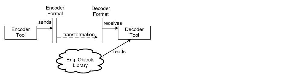
In both scenarios the crucial task for enabling the interaction and data exchange between the tools is to define the semantic links between them, i.e., how the data model of one tool relates to the data model of another tool. A very practical example is the application of referencing schemata as defined in IEC 81346 – Industrial systems, installations and equipment and industrial products – Structuring principles and reference designations [7]. Here three major types of referencing schemata are standardized for function-oriented referencing, location-oriented referencing and product-oriented referencing. The same automation device has to have all three references, but they are applied in different disciplines. For example the function-oriented referencing is applied in control engineering, location-oriented referencing is applied in electrical engineering and product-oriented referencing is used in mechanical engineering. Nevertheless, the engineers (and their engineering tools) have to be able to identify that every time the same automation device is referenced.
These dependencies and relations, when formally defined and formulated in a machine understandable way and in enough detail to allow data interpretation, are called mappings [2]. There exist various techniques to represent mappings, one of which is applying a specific data interchange standard. In the next section we describe in detail various types of mappings that could be required while defining the relations between different tool data models. These requirements were derived from literature analysis [2,5,9] in the field of schema and ontology mapping and the work of the authors within the AutomationML initiative [1] and cooperation projects with automotive industry.
Semantic Mapping Types
This section summarizes mapping types that are relevant in general [8] and could be needed in mechatronic context to define the correspondences between the data models of different engineering tools.
- M1: Value processing. Often the relation between the data model entities on the source and target sides is not “exactly-the-same”, but a function that takes a property value on the source side as an input and returns a property value for the target side as an output, i.e., a certain processing is needed to map the entities. The complexity of this processing varies strongly, from simple string operations to sophisticated mathematical transformations.
- M1.1: String processing. This type of mapping requires using special functions on string values, e.g., “concat”, “sub-string”, “regex”. For instance, the function-oriented referencing has to be translated to a location-oriented referencing by replacing the “=” delimiter with the “+” delimiter, if the same level identifiers are applied.
- M1.2: Data type transformation. Semantically the same entities can be modelled using different data types. For instance, the same attribute of an automation device representing a physical condition can be defined as an integer in one tool and as a real value in another tool.
- M1.3: Math functions. A mapping’s processing can be specified by some mathematical or physical formula. This comprises such simple mathematical operations as addition or multiplication and more complex ones, like finding an integral or logarithm. An example is the calculation of the maximal current and voltage for electrical engineering of a drive, based on the maximal torque necessary within mechanical engineering.
- M1.4: External function calls. This mapping type comprises functions that are not supported by the used technology, but must be additionally implemented. Therefore, it must be possible to call an external function (implemented, e.g., in Java) that will generate a value for a specific object in a target model. For instance, dependencies of locations of metal parts within multi-body simulations in mechanical engineering can be based on models of electric fields which need an additional model solver.
- M2: Granularity. This mapping type is required if the same real-life objects were modelled on different levels of detail. An example are hierarchies like resource hierarchies in manufacturing systems (cell, main function group, function group, etc.), structured differently, e.g., an object on a source side is represented as a set of objects on target side. This is usually the case in mechanical and electrical engineering where electrical engineering has fewer hierarchy levels.
- M3: Schematic differences. This type of mapping implies that there are substantial differences in the way how the same semantics is represented in the source and target models. For example, in mechanical engineering a production resource is modelled as a set of mechanical parts, where some of them are mechanical components controlled by automation devices. These controlled components provide a functional behaviour (production function). In control engineering only the automation devices are considered. Here again the production functions are considered, but now in terms of controller functions of the automation devices. Both sets of behaviour descriptions belong to each other and depend on each other, but have completely different semantics.
- M4: Conditional mappings. This mapping type is needed if a relation between the entities in source and target models exists if and only if a certain condition (or a set of conditions) holds on the source side. For instance, in electrical wiring a communication system repeater only exists if the distance between communication devices exceeds a defined value.
- M5: Bidirectional mappings. An important characteristic of mappings is that they are directional [6], i.e., usually they are specified in a direction from source to target and the data flow cannot occur in the opposite direction. However, for some applications, such as data transformation, it is beneficial to have the opportunity to define bidirectional mappings between engineering objects. It would help to reduce the total amount of mappings, thus facilitating their maintenance. Bidirectional mappings are reasonable for round-trip engineering often occurring in production system engineering, where mechanical engineering specifies activities for electrical engineering to connect defined automation devices, and electrical engineering calls for the mechanical engineering of additional devices.
- M6: Grouping and aggregation. In some cases it is important to group and/or aggregate objects on the source side in order to set the relation to the target model. For instance, several behaviour models (i.e., program organization units) from control engineering have to be subsumed to one behaviour model for simulation in mechanical engineering.
- M7: Restrictions on values. In some cases it can be important to define that a certain property value is mandatory, i.e., this property must always have a value. If such a property participates in a mapping on a target side, but there is no data on a source side to generate the value, this situation must be handled. An example for this case are configuration parameters defined by the production application required in control engineering for control code parameterization, but defined in mechanical engineering.
AutomationML Modelling Capabilities
The AutomationML data exchange format is under development by the AutomationML e.V. [1] and currently within the international standardization process at IEC under the reference number IEC 62714. It is a neutral, open, and XML-based data exchange format that enables the consistent and lossless exchange of engineering information related to manufacturing system topology, geometry, kinematics, and control behaviour and exploits an object-oriented approach [4]. Each AutomationML object may integrate different information elements with different semantics related to different engineering disciplines. AutomationML follows a modular structure and consists of several XML-based data formats, which are combined under one roof, the so-called top-level format. Logically AutomationML is partitioned into descriptions of: plant topology (following CAEX IEC 62424), geometry and kinematics (following COLLADA) and control-related logic data (following PLCopen XML), where COLLADA and PLCopen files are referenced out of CAEX files. Of main interest for this paper is the modelling of the plant topology using CAEX. Here production system components are represented and their semantics is given via roles, e.g., if an object represents a robot, a conveyor, or a work cell.
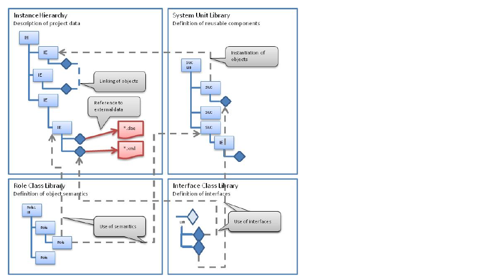
Major modelling means are role class libraries that model object semantics, interface class libraries that model object relations and references to external information, System Unit class libraries that model production system component libraries, and, finally, instance hierarchies with internal elements that model the hierarchy of production system components in a recent project or setting (see Figure 3).
Exploiting these major modelling means to model production system components, there are the following possibilities to model mappings between modelled entities:
- A1: Part – subpart relation in InstanceHierarchy. Within the InstanceHierarchy modelled objects are represented in a part-subpart relation naming which element is a component of a larger element. Here, only a structuring relation can be presented without any properties.
- A2: Mirror objects. Mirror objects contain in their RefBaseClassPath attribute a reference to the original object by giving the GUID of the original object. Here, an “equals” relation of objects is represented.
- A3: Interfaces. Each InternalElement and each SystemUnitClass can contain an interface object representing the link to external information covering possible mapping information, e.g., an InternalElement “robot” within the InstanceHierarchy has an interface object which refers to a COLLADA or PLCopen XML file to assign geometry or behaviour to “robot”.
- A4: Interface – InternalLink combination. Two objects (InternalElements) can be linked by connecting interfaces being sub-objects of the internal elements by an internal link. Here two objects can be linked, where the type of link is given by the type of the used interfaces. Properties of the link cannot be presented.
- A5: Interface – InternalLink – InternalElement combination. Two objects (InternalElements) can be linked by establishing the following chain: InternalElement – Interface – InternalLink – Interface – InternalElement – Interface – InternalLink – Interface – InternalElement. The InternalElement in the middle of this chain represents the semantics of the link, while the interface objects hold the semantics of the individual association points. Properties of the link can be associated to the middle InternalElement by attributes.
- A6: Semantic reference attribute. In each object (independent of InternalElement, SystemUnitClass or Interface) an additional attribute can be modelled carrying a semantic reference. If this reference points to another object, they can be linked.
- A7: RefBaseSystemUnitClassPath attribute. Each InternalElement contains a RefBaseSystemUnitClassPath attribute indicating the SystemUnitClass it is derived from. Thereby type information can be presented.
- A8: RoleRequirement and SupportedRoleClass attribute. Each InternalElement and SystemUnitClass contain RoleRequirement and SupportedRoleClass attributes indicating the RoleClass it is derived from. Thereby semantic information can be presented.
The different possibilities to model mappings are in different ways capable to represent the mapping types given above. Figure 4 summarizes the representation capabilities: “+” denotes that a certain semantic mapping type can be represented using corresponding modelling means in AutomationML; “−” denotes the limited ability of proper representation. It can be seen that each semantic mapping type can be represented in AutomationML; often there are even several ways for mapping representation.
Fig. 4 (matrix of semantic mapping types represented in AutomationML) is available in the original PDF.
Selection of Mapping Type Representations
The proper selection of the mapping type representation in AutomationML, i.e. the identification of the best capability to model a semantic mapping, strongly depends on the application cases. Within the engineering of production systems three major classes of use cases can be distinguished, having strong impact on the way semantic mappings can be modelled.
Mappings crossing file borders
The first class of use cases is characterised by the use of more than one CAEX file covering the relevant information and, thereby, requiring to model semantic mappings between objects located in different files. An example of such a case is the use of different AutomationML files for the mechanical, the electrical and the control engineering part of a project which naturally occurs if these tools have different exporters.
Following the AutomationML standard, internal link objects have to be stored on the lowest common upper object of the interface objects linked. In case of more than one file containing information objects to be mapped, this mechanism cannot be exploited. Thus, in this case the modelling possibilities A4 and A5 have to be excluded. The same holds for the modelling possibilities A1 and A2 as it cannot be guaranteed that objects stand in a hierarchy relation to each other and are mirrored crossing file borders.
Now we can assume two main scenarios of mapping definitions. The first main scenario is the discipline crossing definition of semantics including the semantic based definition of mappings. This can be the case for the mapping types M1.1 (for example by defining discipline specific naming rules for common objects), M1.2 (for example by defining discipline specific data types for common objects), M3 (for example defining discipline specific structures for common objects) and M7 (for example by defining discipline specific conditions for common objects). In this scenario the mappings can be modelled by using a semantic identifier as it is given by roles. Nevertheless, this mapping is then only implicitly defined.
In the second scenario the mapping is defined individually depending on the engineering discipline and/or the application case of the mapping. In this case the generic representation of mappings by roles, system unit classes or semantic references cannot be applied and A6, A7 and A8 need to be excluded.
As main consequence only the mapping modelling based on external interfaces (modelling type A3) is applicable in the case of two or more CAEX files involved. In this case the information objects to be interlinked have to fulfil the following conditions:
- Each partner side of the mapping has to get an interface object derived from the generic interface class
ExternalDataConnector. This interface object has to contain attribute objects representing the necessary information of the mapping like the mathematical function for M1.3 or the condition for M4. - Each partner of the mapping has to be uniquely identifiable. This should be given by the ID of an object or the path to the object and unique naming.
- Within the
refURIattribute of the interface object of both partners the other partner should be referenced by using file name and unique object identification.
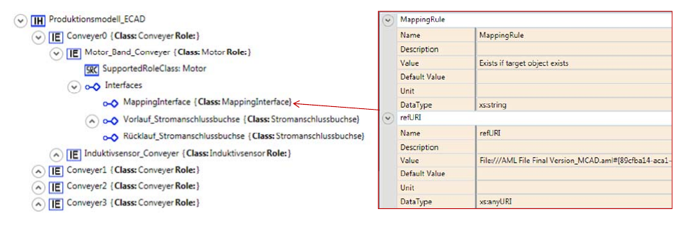
As an example of this mapping representation let’s assume a conveyor based transportation system. Within this system we consider the mechanical and the electrical engineering. Within the electrical engineering a drive should only be considered if this drive will be associated to a conveyor belt. Thus we have a mapping of type M4.
Figure 5 depicts a drive object named Motor_Band_Conveyer within a conveyor object Conveyer0 in the ECAD generated AutomationML file. This drive object contains an interface object MappingInterface representing the mapping to the conveyor belt object of the related MCAD emerging AutomationML file. The named interface has two attributes. The refURI attribute contains the reference to the unique identity of the target object while the MappingRule attribute describes the type of mapping.
Mappings crossing instance hierarchy borders
The second class of use cases is characterised by the use of one CAEX file covering the relevant information. Nevertheless, the different engineering disciplines involved are distinguished within two or more instance hierarchies. Thereby, semantic mappings between objects cover mappings between objects of different instance hierarchies within this class.
As named above, also in this case the modelling possibilities A4 and A5 for mappings cannot be applied as there is no common upper object for the objects to be mapped. Thus, there is also no common hierarchy applicable, excluding A1. The use of external interfaces to map between objects within the same file is omitted by definition, i.e. A3 is excluded.
Mirror objects as supposed in A2 can identify internal elements in the same file and place them in a different hierarchy. But it is impossible to change any of its content. Thus, it is impossible to adapt them in another instance hierarchy to the needs of the other engineering domain. Hence, also A2 is not applicable.
The discussion related to common semantic definitions given above can be applied in the same way also in this class of use cases. The only exception is the application of semantic references defined by the RefSemantic object within attributes.
Fig. 6 (schema of attribute type with semantic reference) is available in the original PDF.
The RefSemantic object can carry an identifier enabling the identification of other objects while the attribute hosting the reference can carry the description of the mapping.
As main consequence the mapping modelling based on RefSemantic within attributes (modelling type A6) is best applicable in the case of one CAEX file with more than one instance hierarchy involved. In this case the objects to be interlinked have to fulfil the following conditions:
- Each partner of the mapping has to get a specially named attribute. This attribute has to contain in its value the necessary information of the mapping like the mathematical function for M1.3 or the condition for M4.
- Each partner of the mapping has to be uniquely identifiable. This should be given by the ID of an object or the path to the object and unique naming.
- Within the
RefSemanticXML attribute of the CAEX attribute of both partners the other partner should be referenced by using the unique object identification.
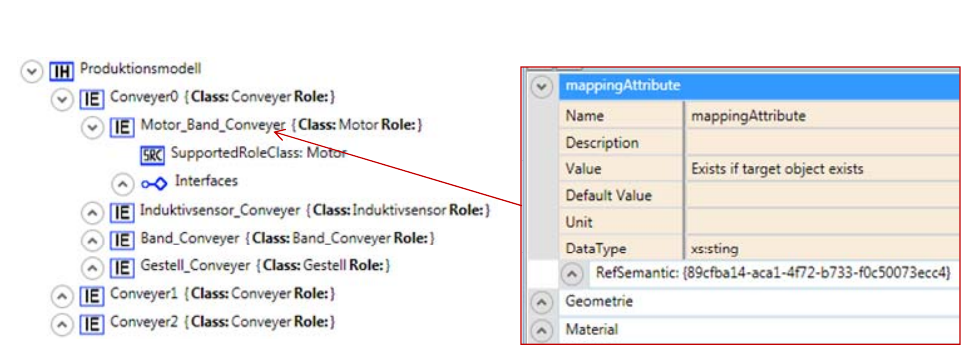
Let’s come back to the drive example above. Now we have two instance hierarchies for MCAD and ECAD within the same AutomationML file. Exploiting the modelling type A6 the drive object in the instance hierarchy covering the ECAD information contains an attribute named mappingAttribute describing the type of mapping while the RefSemantic information within this attribute contains the unique identification of the conveyor belt object within the MCAD related instance hierarchy. The result is depicted in Figure 7.
Mappings within one instance hierarchy
The third class of use cases is characterised by the application of exactly one CAEX file with one instance hierarchy exploited to model all relevant engineering data even if they are from different disciplines.
Following the discussions above the use of external interfaces (modelling type A3) as well as the use of common semantic representations (modelling types A7 and A8) should be avoided. But all other types can be applied. Nevertheless, still this leads to a broad selection of possibilities for mapping representation.
If we consider the different mapping types in detail we can see that there are two main groups of mappings: mappings between individual objects (covering M1, M4, M5, and M7) and mappings between groups of objects with two and more elements (covering M2, M3, and M6).
For mappings between individual elements the easy identification of mapping partners is essential in combination with the description of the mapping rules. This is given in the easiest way in the case of the use of A6 as described above.
An extended version of the use of the RefSemantic based identification of mapping partners is the use of either the chain of an interface, an internal link, and a second interface (modelling type A4) or its extended version of a chain interface, internal link, interface, internal element, interface, internal link, and interface (modelling type A5) as used in the case of communication network modelling for communication link description.
Modelling type A4 makes the identification explicit in the data model but moves the modelling of the mapping rules to an attribute of the interfaces.
In A5 the mapping rules are associated to the intermediate internal element. In contrast to modelling type A4 here the object hosting the mapping rules is uniquely identifiable by a UUID. Thus this version is the richer one with respect to expressiveness.
This makes it also better applicable for the second group of mappings linking more than two elements together. Here a kind of star structure of interface, internal link, and interface chains to the same internal element hosting the mapping information seems to be best applicable.
As main consequence the mapping modelling based on RefSemantic (modelling type A6) and Interface – InternalLink – Element combinations (modelling type A5) are best applicable in the case of one CAEX file with one instance hierarchy, as depicted in Figure 8.
Fig. 8 (matrix of mapping modelling within one instance hierarchy) is available in the original PDF.
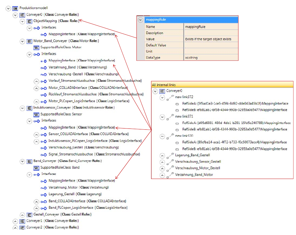
Now let’s extend the example above by an inductive sensor, which also should be existent only if the conveyor belt exists and all related information is in the same instance hierarchy. Now we create a mapping object in the conveyor object hosting an attribute representing the mapping type. This object and all mapped objects will have a new MappingInterface used to link the mapped objects by internal links. The result is given in Figure 9.
Application of OCL for Mapping Description
The remaining open issue is the representation of the mapping type within the attribute. Here different technologies can be applied. One of the most appropriate seems to be OCL.
The Object Constraint Language (OCL) [15, 16] is a declarative language to define rules on UML models. These rules specify constraints and object query expressions that can be used for navigating, transforming, querying and providing views on UML models. OCL is currently a part of the UML standard. OCL expressions use vocabulary of UML class diagrams. One can distinguish following parts within an expression: a) context specifies the element we are talking about; b) self indicates the current object and c) result denotes the return value.
Following the examples given above a rule calling for the existence of an electrical interface within a mechatronic object can be modelled as given in Figure 10. Such expressions can also be applied within the attributes named above using the unique object identifiers as indicators of the objects intended.
# Every MechatronicObject has exactly one ElectricalInterface
context: MechatronicObject
inv: self.reference->select(i|i.oclIsKindOf(ElectricalInterface))->size = 1
Fig. 10 (OCL example, including the accompanying class diagram) is available in the original PDF.
Conclusions and Further Work
In this paper we investigated how semantic mappings between automation systems engineering model views can be represented in the data exchange standard AutomationML. While the analysis showed that all required mapping types can be represented in AutomationML, we also found that there is no clear guideline in the AutomationML context on how to represent relations and dependencies between model views. Such a guideline depends on the application case of the mapping connecting objects of different files or the same file, and different instance hierarchies or the same hierarchy. Related to the three emerging possibilities of application cases we have identified a first set of applicable mapping models providing relations in a machine-understandable way to enable the automation of quality assurance processes in automation engineering.
Initial work has been done by the AutomationML consortium considering special types of dependencies and relations. Examples are the consideration of the dependencies between products, production processes and production resources (PPR concept) [12] and the representation of graph based structures [13]. Future work will include investigating guidelines for engineers and tools on best practices for representing links between engineering models extending current practice.
Acknowledgment
This work has been supported by the Christian Doppler Forschungsgesellschaft, the Federal Ministry of Economy, Family and Youth and the National Foundation for Research, Technology and Development – Austria; and by the Erasmus Mundus Action 2 Program of the European Union.
References
[1] AutomationML website: www.automationml.org.
[2] Z. Bellahsene, A. Bonifati, and E. Rahm. Schema matching and mapping. Vol. 20. Heidelberg (DE): Springer, 2011.
[3] T. Berners-Lee, J. Hendler, and O. Lassila. “The semantic web.” Scientific American 284, no. 5 (2001): 28–37.
[4] R. Drath, ed., Datenaustausch in der Anlagenplanung mit AutomationML: Integration von CAEX, PLCopen XML und COLLADA. Springer DE, 2010.
[5] J. Euzenat and P. Shvaiko. Ontology matching, vol. 18. Heidelberg: Springer, 2007.
[6] C. Ghidini, L. Serafini, and S. Tessaris. “On relating heterogeneous elements from different ontologies.” In Modeling and Using Context, pp. 234–247. Springer Berlin Heidelberg, 2007.
[7] International Organization for Standardization: Industrial systems, installations and equipment and industrial products – Structuring principles and reference designations – Part 1: Basic rules, 2009.
[8] O. Kovalenko, C. Debruyne, E. Serral, and S. Biffl. “Evaluation of Technologies for Mapping Representation in Ontologies.” In On the Move to Meaningful Internet Systems: OTM 2013 Conferences, pp. 564–571. Springer Berlin Heidelberg, 2013.
[9] F. Legler and F. Naumann. “A Classification of Schema Mappings and Analysis of Mapping Tools.” In BTW, vol. 103, pp. 449–464, 2007.
[10] H. Wache, T. Voegele, U. Visser, H. Stuckenschmidt, G. Schuster, H. Neumann, and S. Hübner. “Ontology-based integration of information – a survey of existing approaches.” In IJCAI-01 workshop: ontologies and information sharing, vol. 2001, pp. 108–117, 2001.
[11] D. Winkler, T. Moser, R. Mordinyi, W. D. Sunindyo, S. Biffl. “Engineering Object Change Management Process Observation in Distributed Automation Systems Projects”, Proc. of the 18th EuroSPI Conference, Roskilde, Denmark, 2011.
[12] M. Schleipen, R. Drath. “Three-view-concept for modeling process or manufacturing plants with AutomationML”. In: Proceedings of the 2009 IEEE Conference on Emerging Technologies Factory Automation (ETFA 2009), pp. 1519–1522, Palma de Mallorca, Spain, September 2009.
[13] A. Lüder, N. Schmidt, S. Helgermann. “Lossless exchange of graph based structure information of production systems by AutomationML”, In Proceedings of 18th IEEE International Conference on Emerging Technologies and Factory Automation (ETFA 2013), Cagliari, Italy, September 2013.
BibTeX
@inproceedings{biffl2014semantic,
  author    = {Biffl, Stefan and Kovalenko, Olga and L{\"u}der, Arndt and Schmidt, Nicole and Rosendahl, Ronald},
  title     = {Semantic Mapping Support for Mechatronic Objects in {AutomationML}},
  booktitle = {Proceedings of the 3rd AutomationML User Conference},
  address   = {Blomberg, Germany},
  month     = oct,
  year      = {2014},
  publisher = {AutomationML e.V.},
  url       = {https://www.automationml.org/conferences/conference-highlights/semantic-mapping-support-for-mechatronic-objects-in-automationml/}
}
How to Cite
S. Biffl, O. Kovalenko, A. Lüder, N. Schmidt, R. Rosendahl: “Semantic Mapping Support for Mechatronic Objects in AutomationML”, Proceedings of the 3rd AutomationML User Conference, Blomberg, Germany, 7–8 October 2014.
This page is a text rendering of the original conference paper, published for accessibility and search. The PDF is the authoritative version. Figures 1, 4, 6, 8 and 10 are available in the PDF; the capability matrices in Figures 4 and 8 could not be reliably reconstructed from the PDF and should be read there. If you are an author and would like a correction, please contact office@automationml.org.